Fusion 360 cup holder: modelling, step by step
By Admin, 09/09/2026 · 9 min read

Fusion 360 workshop
Fusion 360 cup holder: modelling, step by step
Build the clamp, add the cup body, cut the cavity, and round the edges. The dimensions are given beside each step. Set the desk thickness as a parameter so you can adjust the fit later.
Part
Model dimensions
The C clamp grips the desk edge and the cup joins the closed wall of the clamp. The five checkpoints build the C profile, add the drum, cut the cup, add fillets and turn the desk slot into a parameter.
03 The build
C1 The C profile
Create Sketch on the XZ plane

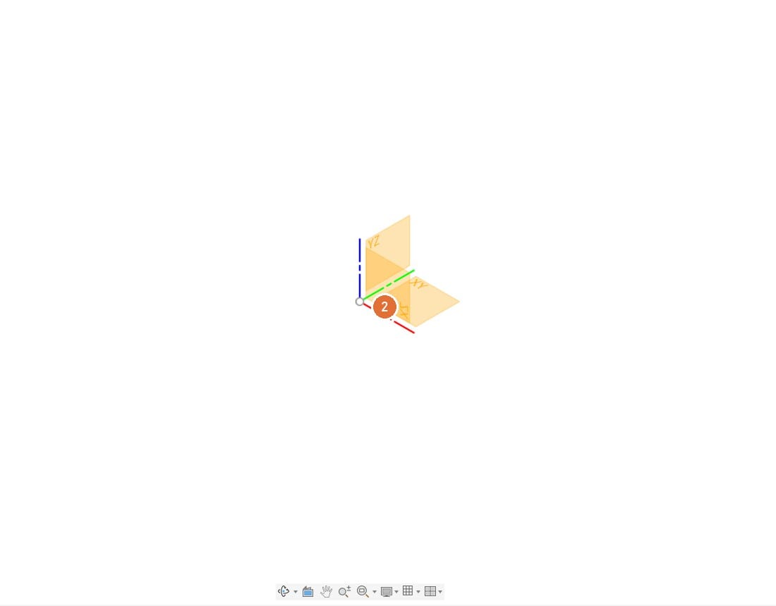
- 1Create Sketch: First icon in the CREATE group. The three origin planes appear in the middle of the screen.
- 2XZ plane: Select the origin plane labelled XZ. Use the plane label rather than its apparent direction in the current view.
On screen: The ViewCube reads FRONT, a grid fills the canvas and the toolbar switches to the SKETCH tab.
Rectangle: 40 wide, 60 tall, from the origin

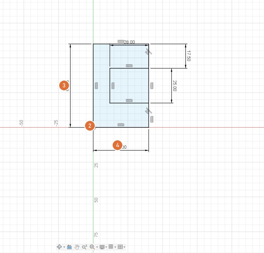
Shown with the slot rectangle from the next step already drawn.
- 1Rectangle: CREATE group, or press R.
- 2Origin: Click the origin point for the first corner.
- 360.00: Enter 60 mm in the height field. Check the active dimension, then press Tab to switch fields.
- 440.00: Enter 40 mm in the width field and press Enter. Confirm that the origin corner and both dimensions are constrained.
R, click the origin, 60, Tab, 40, EnterOn screen: A black rectangle above and to the right of the origin, 40 wide and 60 tall. Blue geometry still has movement available; check its dimensions and constraints.
Second rectangle: the desk slot, 28 by 25
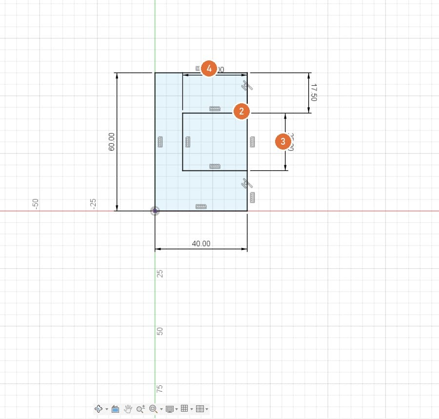
- 1Rectangle: R again.
- 2Right edge: First corner on the right edge of the block, about a third of the way down. The edge highlights and the corner snaps onto it.
- 325.00: Drag left and down. Type 25, Tab. The slot height.
- 428.00: Type 28, Enter. The slot depth.
R, click on the right edge, 25, Tab, 28, EnterOn screen: A second rectangle inside the first, open on the right. Its vertical position is still blue.
Dimension the slot 17.5 mm from the top

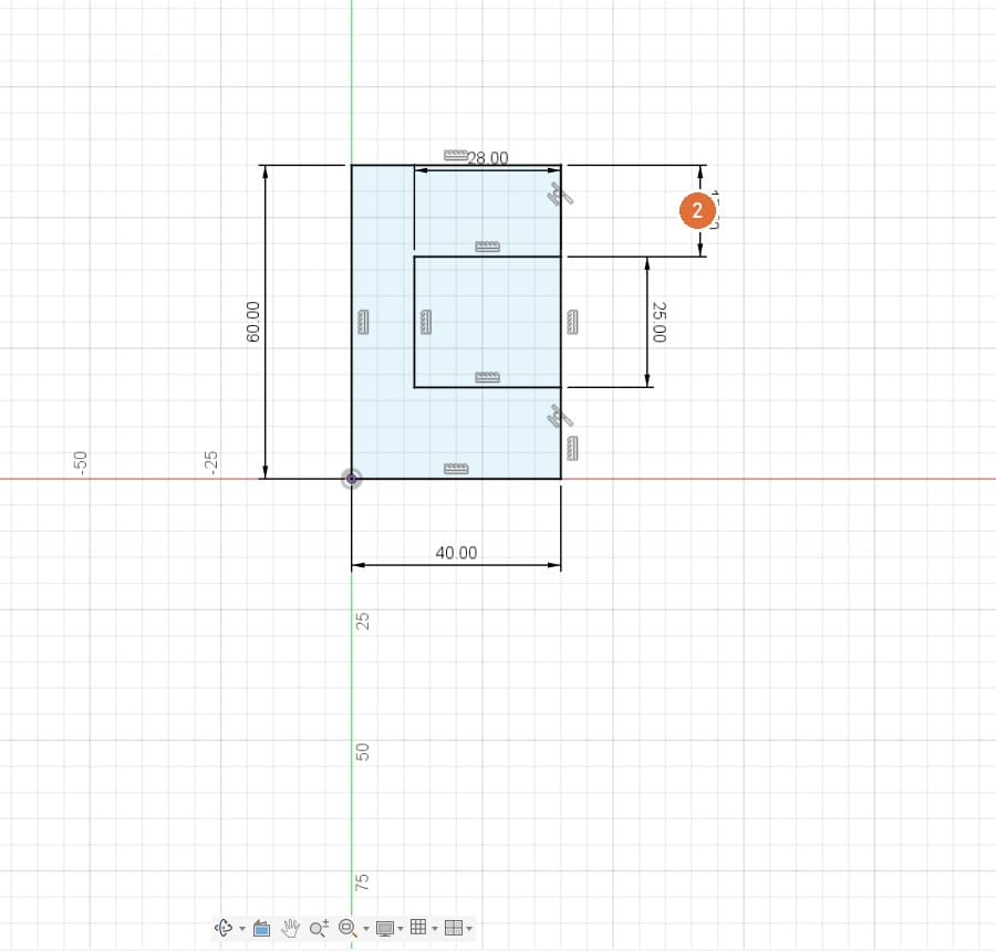
- 1Sketch Dimension: CREATE group, or press D.
- 217.50: Click the top line of the slot, then the top line of the block, move right, click to place. Type 17.5, Enter.
D, slot top line, block top line, click, 17.5, EnterOn screen: Every line is black. The slot is centred: (60 - 25) / 2 = 17.5.
Trim the two edge segments inside the slot

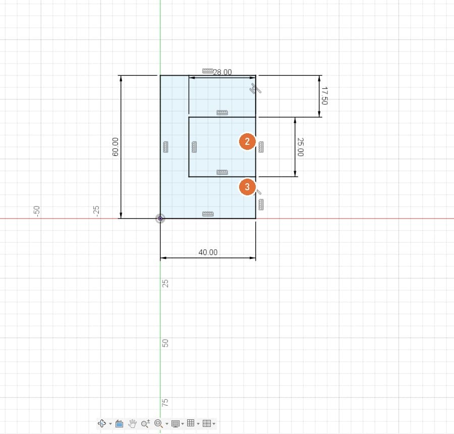
- 1Trim: MODIFY group, or press T.
- 2The edge inside the slot: Hover the block edge between the two slot lines. It turns red. Click.
- 3The same place again: Two lines sit on top of each other there: the block edge and the slot side. Click once more so both are gone and one C-shaped profile remains.
T, click the red segment, click it againOn screen: The shaded area is now C-shaped. If the shading disappears a needed line was trimmed: Ctrl+Z.
Finish Sketch, then Extrude 30 mm

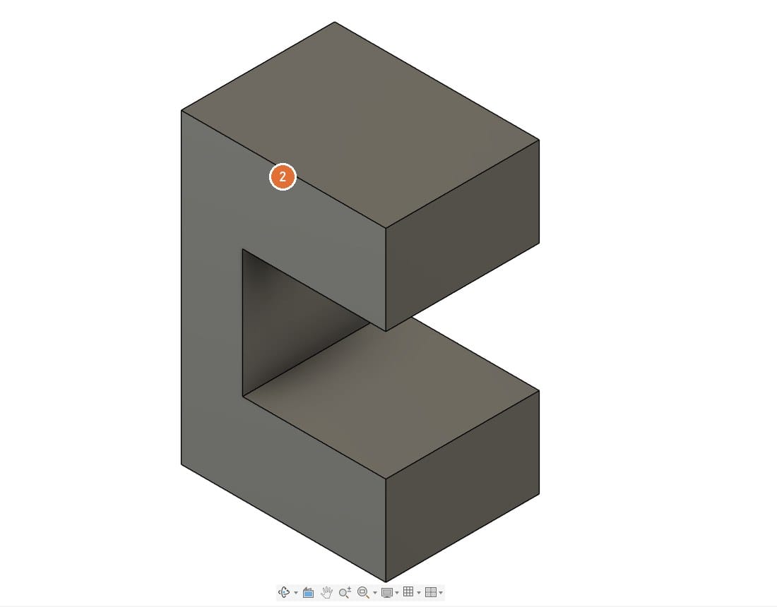
- 1Extrude: Click FINISH SKETCH (green tick, top right) first. Then CREATE > Extrude, or press E.
- 2The C profile: Click inside the C. It highlights blue and an arrow appears.
30, Enter (Operation: New Body)On screen: A grey C block 30 mm deep. Body1 under Bodies in the browser; Sketch1 and Extrude1 in the timeline, bottom left. This is checkpoint 1.
03 The build
C2 The cup body
Sketch on the XY plane: an 80 mm circle

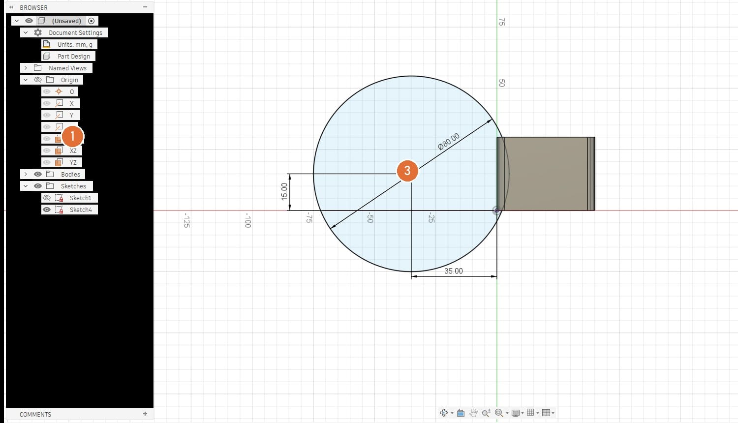
- 1XY under Origin: Create Sketch, then click XY in the browser (expand Origin). This is the plane the clamp stands on.
- 2Circle: CREATE group, or press C.
- 3Centre: Click about 35 mm left of the block and 15 mm above the red axis. Type 80, Enter.
C, click, 80, EnterOn screen: A blue circle overlapping the closed side of the block. The ViewCube reads TOP.
Dimension the centre: 35 from the wall, 15 along it

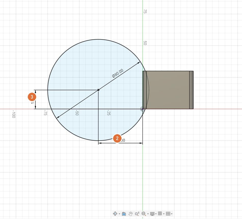
- 1Sketch Dimension: Press D.
- 235.00: Click the circle centre, then the origin, pull down, click. Type 35, Enter.
- 315.00: D again. Click the centre, then the red X axis, pull left, click. Type 15, Enter.
D, centre, origin, click, 35, Enter, D, centre, X axis, click, 15, EnterOn screen: The circle turns black. Its centre sits 35 mm behind the closed wall, so the circle overlaps the wall by 5 mm.
Finish Sketch, Extrude 28 mm, Join

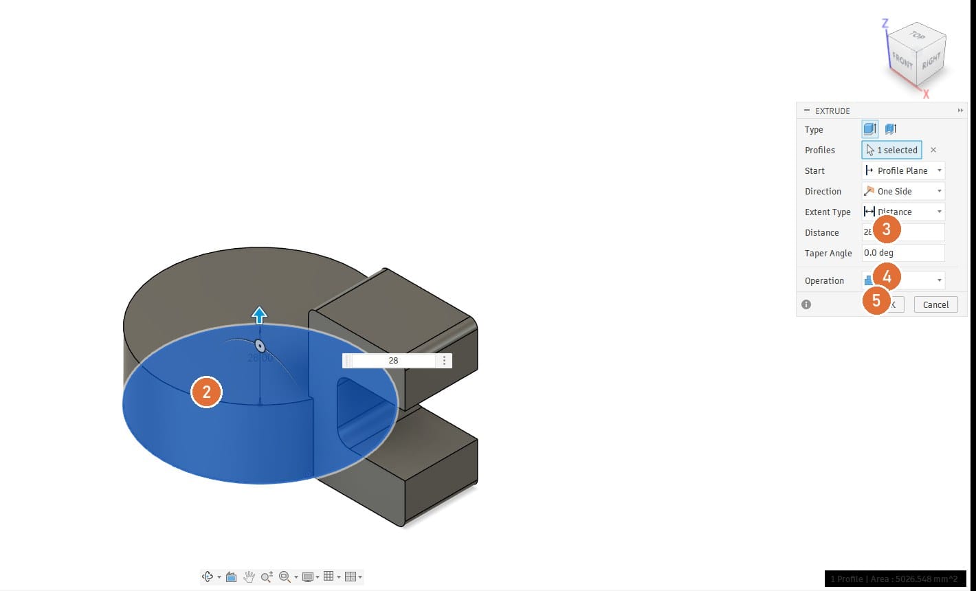
- 1Extrude: Select a closed profile, then check the distance and operation in Extrude.
- 2The circle: Click inside it.
- 3Distance: 28. Upwards, out of the plane.
- 4Operation: Join. If it reads New Body, change it.
- 5OK
28On screen: A drum joined to the clamp. Bodies in the browser still shows one entry, Body1. This is checkpoint 2.
Checkpoint 2: one body, drum and clamp
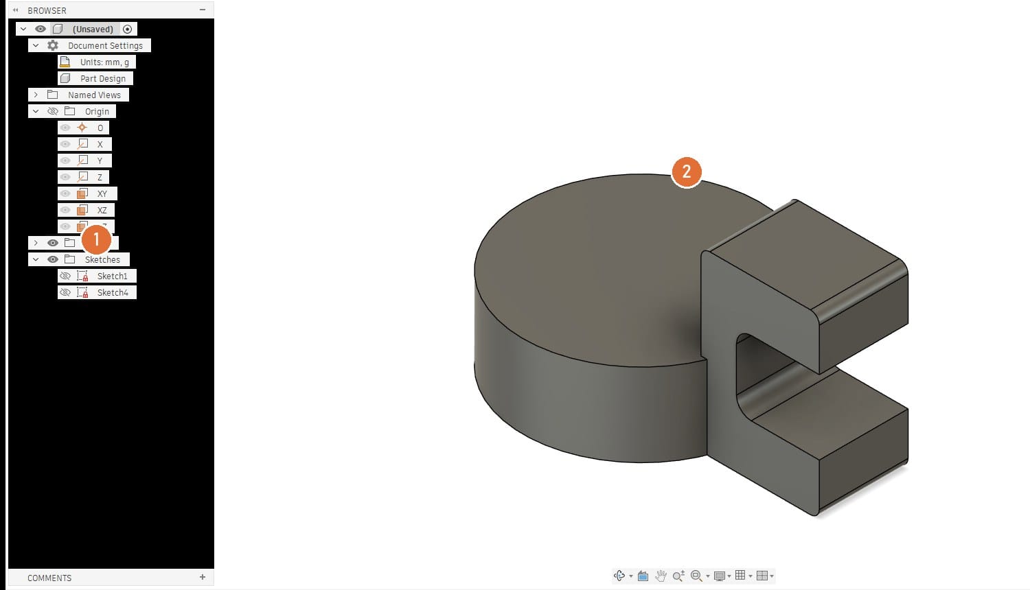
- 1Bodies: Expand it. One entry means the drum joined. Two entries means it did not.
- 2Drum: 80 mm across, 28 tall, standing on the same base as the clamp.
On screen: Timeline: Sketch1, Extrude1, Sketch2, Extrude2.
03 The build
C3 The cup
Sketch on top of the drum: a 70 mm circle

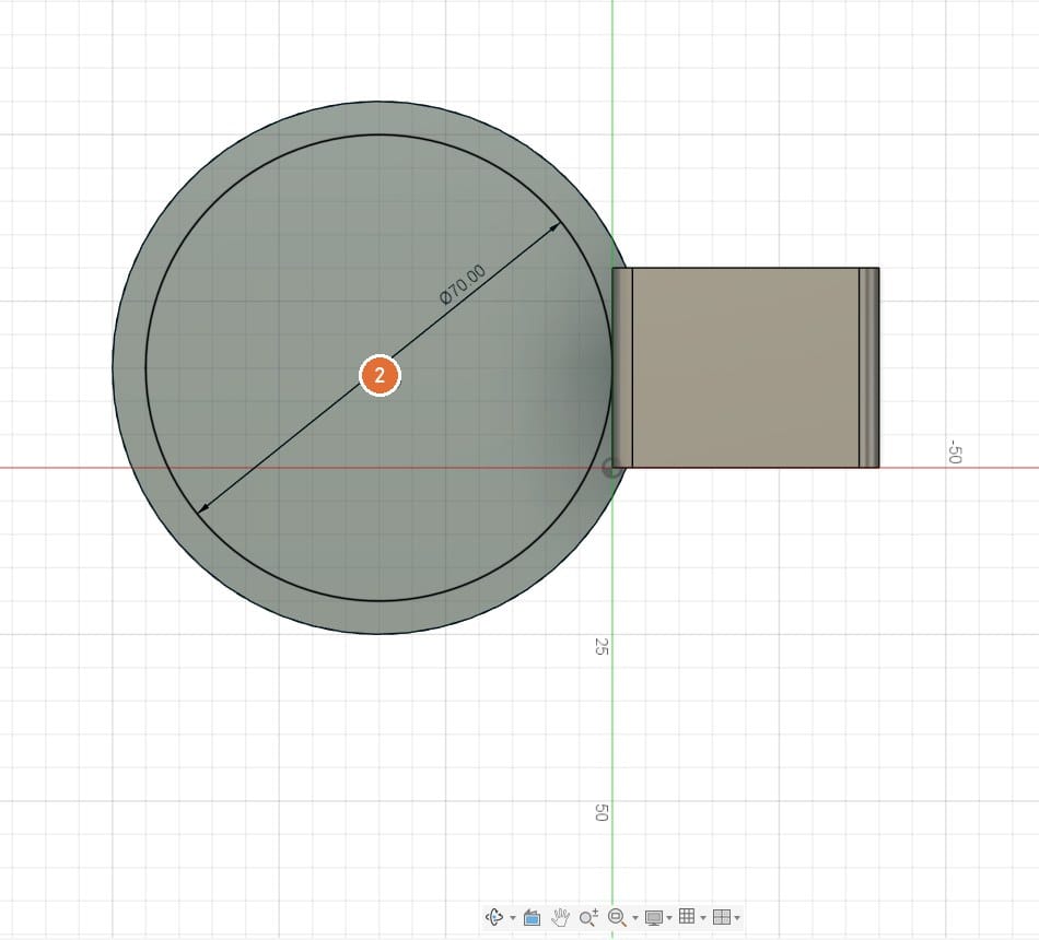
- 1Circle: Create Sketch, click the flat top of the drum, then press C.
- 2Centre snap: Hover the middle of the face until the centre marker appears, click. Type 70, Enter.
C, centre of the face, 70, EnterOn screen: A black circle inside the drum outline. Black at once, because its centre is locked to the face centre.
Extrude -20 mm: Cut
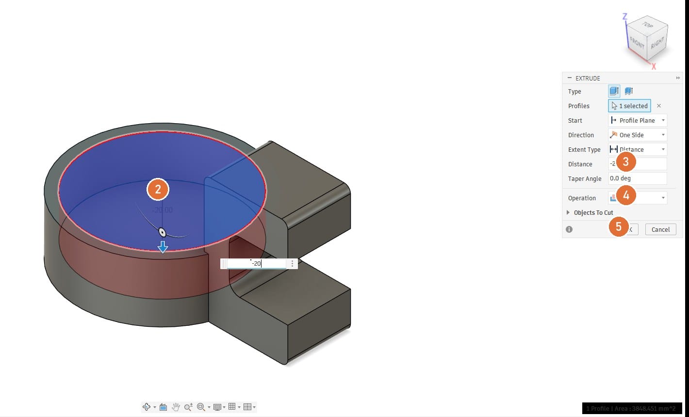
- 1Extrude: Select a closed profile, then check the distance and operation in Extrude.
- 2Inside the circle: Click. The disc highlights blue.
- 3Distance: -20. Minus, so it goes down into the drum.
- 4Operation: Cut. Fusion picks it because the profile sits inside a body. Check it.
- 5OK
-20On screen: The preview goes red inside the drum: material being removed.
Checkpoint 3: the cup, 8 mm floor and 5 mm wall
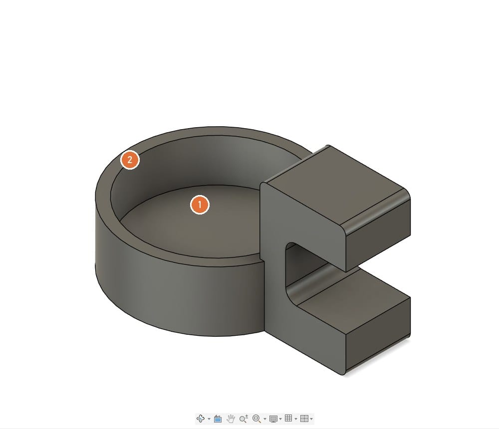
Shown with the C4 fillets already on the clamp.
- 1Floor: 28 - 20 = 8 mm thick.
- 2Wall: (80 - 70) / 2 = 5 mm, and it runs straight into the clamp wall.
On screen: Home view: the house icon above the ViewCube. Timeline has six features.
03 The build
C4 Fillets
Edit Sketch1 from the timeline, fillet a corner

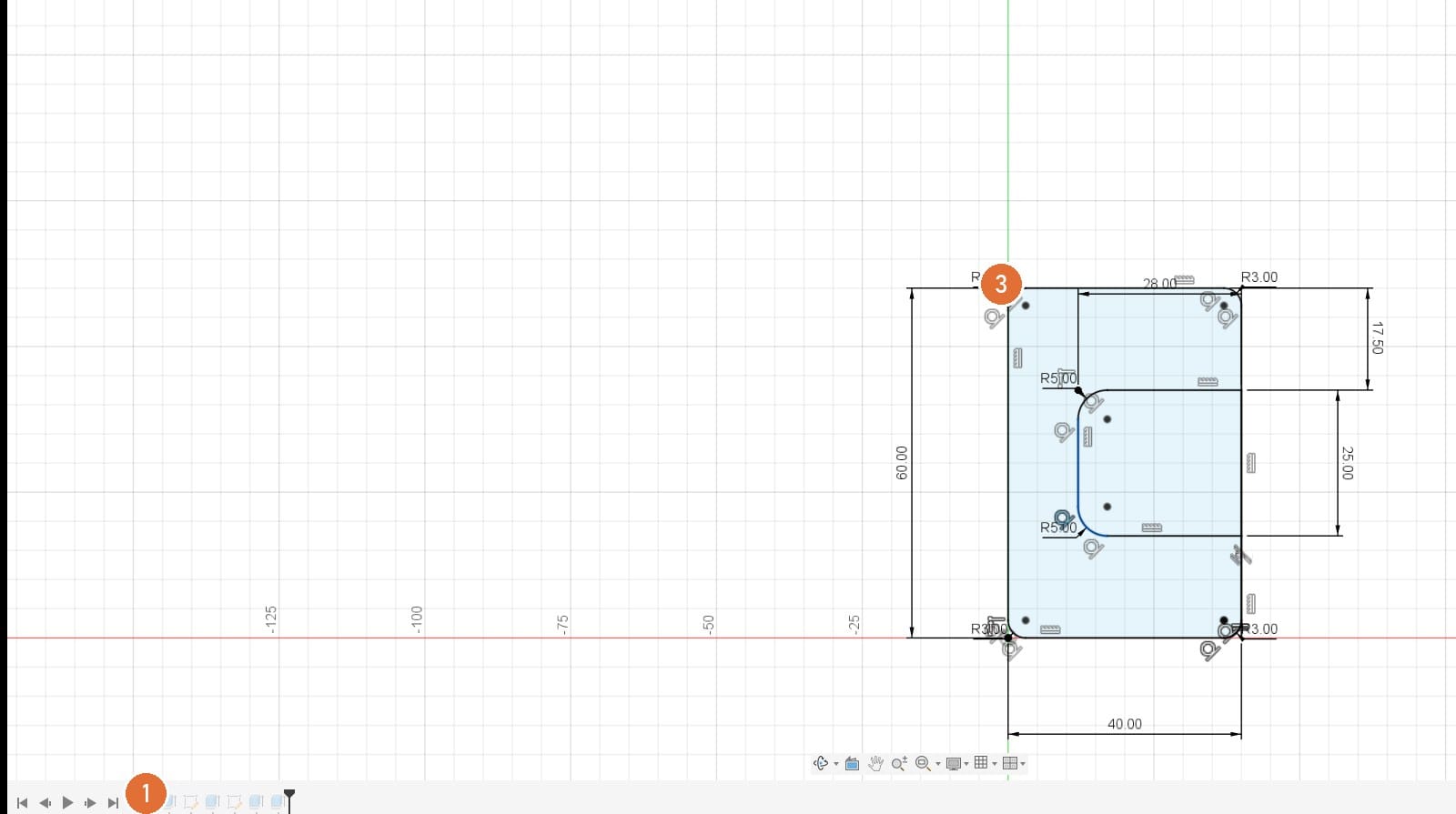
Shown with all six fillets already in place.
- 1Sketch1 in the timeline: Double-click the first icon, bottom left. The model rolls back to the C profile and the sketch opens.
- 2Fillet: MODIFY group of the SKETCH tab.
- 3A corner: Click the top line, then the left line. A fillet appears with an R label. Double-click the label, type 3, Enter.
3On screen: A 3 mm radius on that corner, labelled R3.00.
Four outside corners at 3 mm, two slot corners at 1 mm
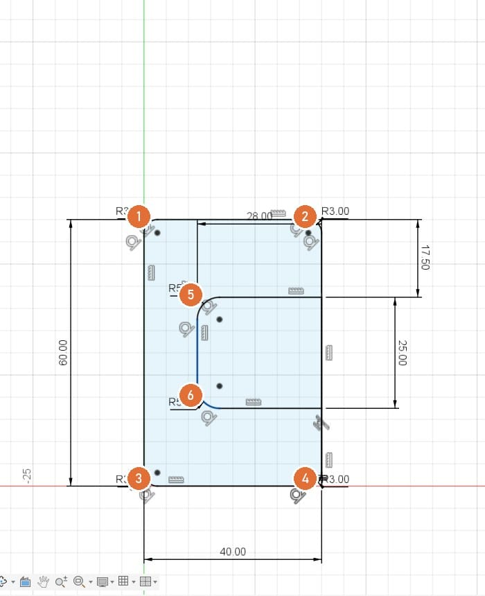
Capture taken before the slot radii were changed from 5 to 1.
- 1Top left, 3: Top line, then left line.
- 2Top right, 3: Top line, then right line.
- 3Bottom left, 3: Bottom line, then left line.
- 4Bottom right, 3: Bottom line, then right line.
- 5Slot top, 1: Inside the slot, at its closed end. Small, so a square desk edge still seats.
- 6Slot bottom, 1: Same. Then FINISH SKETCH.
3, 3, 3, 3, 1, 1On screen: Six fillets, six R labels, everything still black.
Checkpoint 4: everything downstream rebuilds
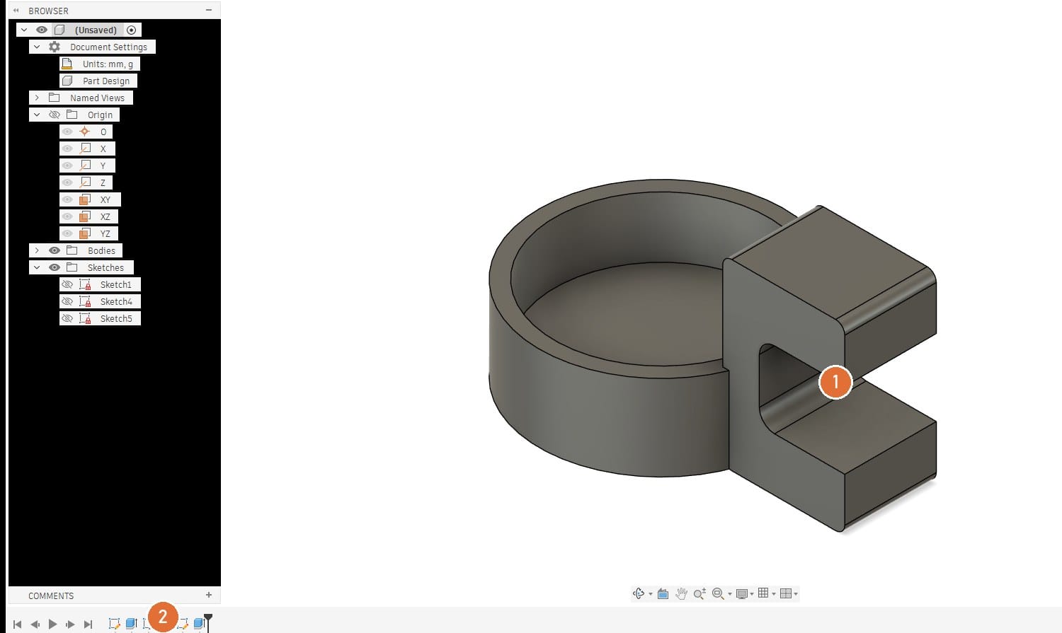
- 1Rounded corners: The extrude, the drum and the cup all rebuilt on the new profile. Nothing else needed editing.
- 2Timeline: Still six features. A yellow triangle on one means a fillet consumed a line the slot needed: Ctrl+Z, smaller radius.
On screen: Home view. The slot has rounded inner corners; the cup is untouched.
03 The build
C5 Parameters
Change Parameters: a user parameter called desk

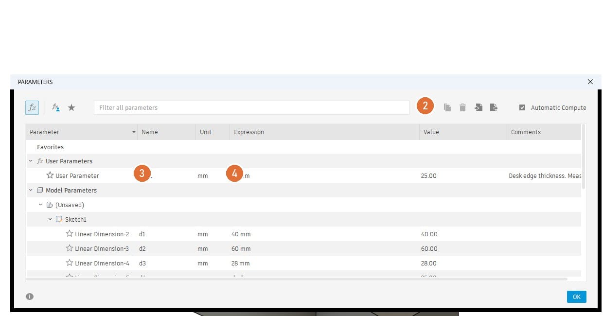
- 1MODIFY > Change Parameters: Bottom of the MODIFY menu. A table opens listing every dimension in the model.
- 2+ beside User Parameters: Name desk, unit mm, expression 25. OK.
- 3desk: Appears under User Parameters.
- 425 mm: Its expression. Measure the desk it is for; 25 here.
desk mm 25On screen: One user parameter above the Model Parameters list.
Point the slot dimensions at the parameter
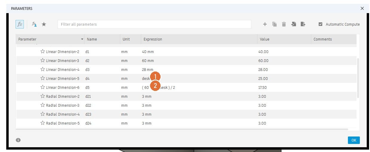
- 1d4 expression: Linear Dimension-5 is the slot height, 25 mm. Double-click its expression cell, type desk, Enter.
- 2d5 expression: Linear Dimension-6 is the 17.5. Type ( 60 mm - desk ) / 2 so the slot stays centred.
desk
( 60 mm - desk ) / 2
On screen: Values still read 25.00 and 17.50. The model has not moved; it now knows where the numbers come from.
Change desk to 30, then 20, then back to 25
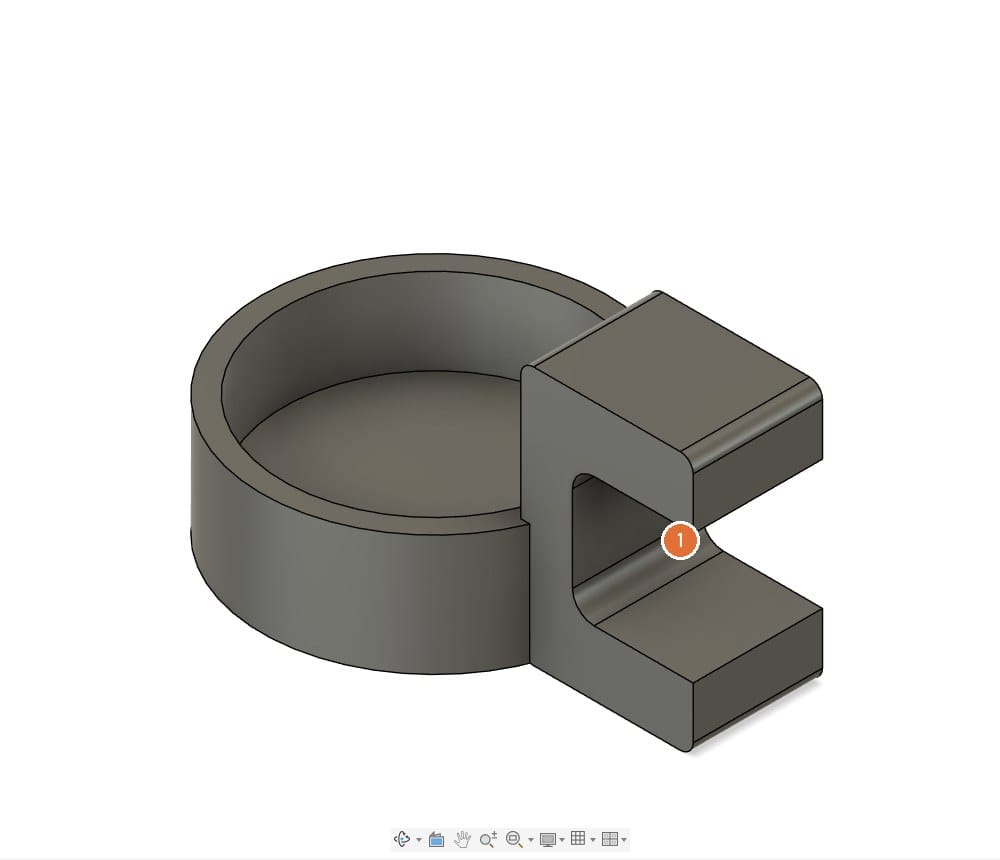
- 1The slot: Only the slot and its two 1 mm fillets move. The cup, the drum and the outside corners stay put.
30, OK. Then 20. Then 25.On screen: The part rebuilds each time in under a second. Ctrl+S: this file is checkpoint 5 and the one both simulations use.
Faults
Common sketch and extrude errors
What you see, what it usually means, and the fix.
Related articles

Fusion 360 to Bambu Studio: 3MF export and slicing, step by step
Export the Fusion 360 cup holder as a 3MF file and check print orientation and slicing in Bambu Studio.

Fusion 360 thermal simulation, step by step
Set up the Fusion 360 thermal study for the cup holder and compare material choices for a hot cup wall.

Fusion 360 static stress simulation, step by step
Set up the Fusion 360 static stress study for the cup holder and read safety factor, von Mises stress and displacement.