Metal touch sensor
By Admin, 15/09/2026 · 4 min read

37-in-1 kit, module 33
KY-036: Metal touch sensor
Reacts when a finger touches the bare metal leg. Plug it in, upload the sketch, then change the thing it senses and watch the reading.
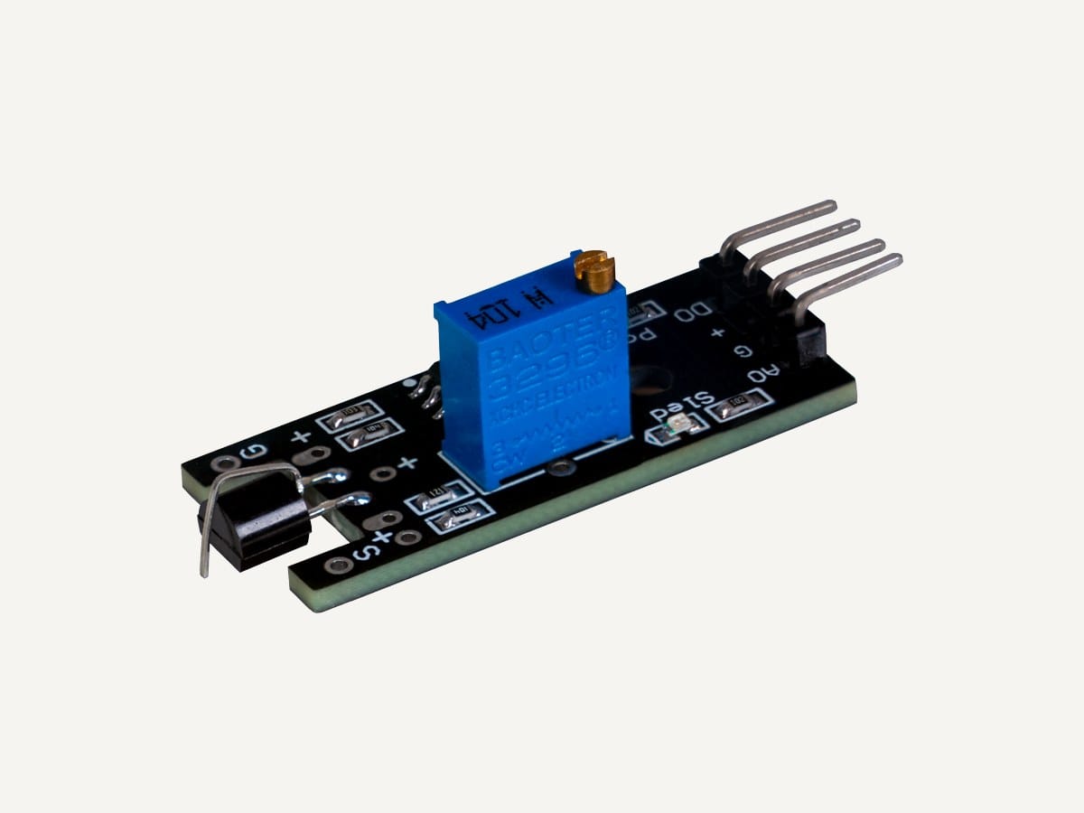
How it works
Metal touch sensor
What is going on
Connections
Wiring to the Arduino Nano on its expansion shield
The pins below match the sketch further down this page; change one and change the other.
Power off first
Unplug the USB cable before you plug in, move or remove any module.
A lead plugged in live can touch the wrong pin for a moment, and 5 V on a signal pin is how a module dies. Unplug, wire, check the letters, then plug the cable back in.
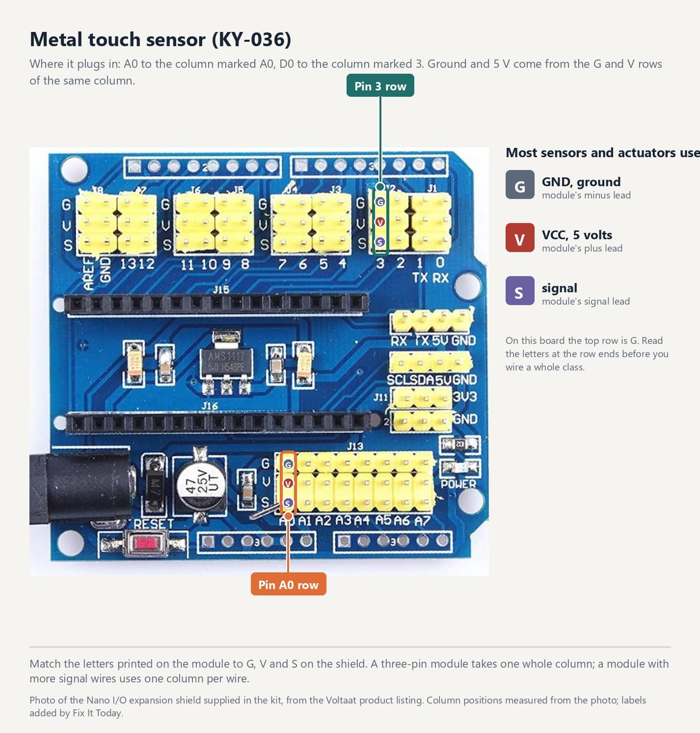
Read the letters on the shield
Starter sketch
Code you can copy and upload
Every sketch on these pages is compiled for the Arduino Nano before it is published. The pin numbers at the top match the connection table above.
Try first
Touch the metal leg. Then touch it while holding the laptop's metal case with the other hand.
The quickest way to see it respond.
Unplug the USB cable. Plug the module into the column shown above, minus to G, plus to V, signal to S.
Plug the USB cable back in. Copy the sketch, upload it, and open Tools > Serial Monitor at 9600 baud.
Do the thing the module senses and watch the reading, the L LED, or the sound respond.
Reference
The Joy-IT page has the datasheet figures and examples for other boards; the repository has the original vendor files.
KY-numbered kit repository: datasheets and original examples
Arduino Nano and I/O expansion shield wiring
Arduino Nano and DHT11 electronics workshop
All 37 modules
Survey and feedback
Help improve MakerAccess
Have an idea for what MakerAccess should stock, improve, or explain next? Share it in the survey. If you bought or used a product and want to comment on the item itself, use the product feedback form.
Do the surveyProduct feedback form

