We use cookies to understand how the site is used and improve it.
Arduino Nano and I/O Expansion Shield Wiring
Arduino Nano and I/O Expansion Shield Wiring
By Admin, 03/09/2026 · 13 min read
The Arduino Nano pin map, the four pins that behave differently, how the I/O expansion shield's Ground-Voltage-Signal headers work, and the ideas the workshop sketches rely on.
Electronics reference
Arduino Nano and I/O expansion shield wiring
Nano pin functions, expansion-shield connections and the electronics concepts used in the workshop. Written for the USB-C Nano and the Nano I/O expansion shield used in the Fix It Today electronics workshops.
Thirty pins. The notes below cover the six that don't behave like the rest.
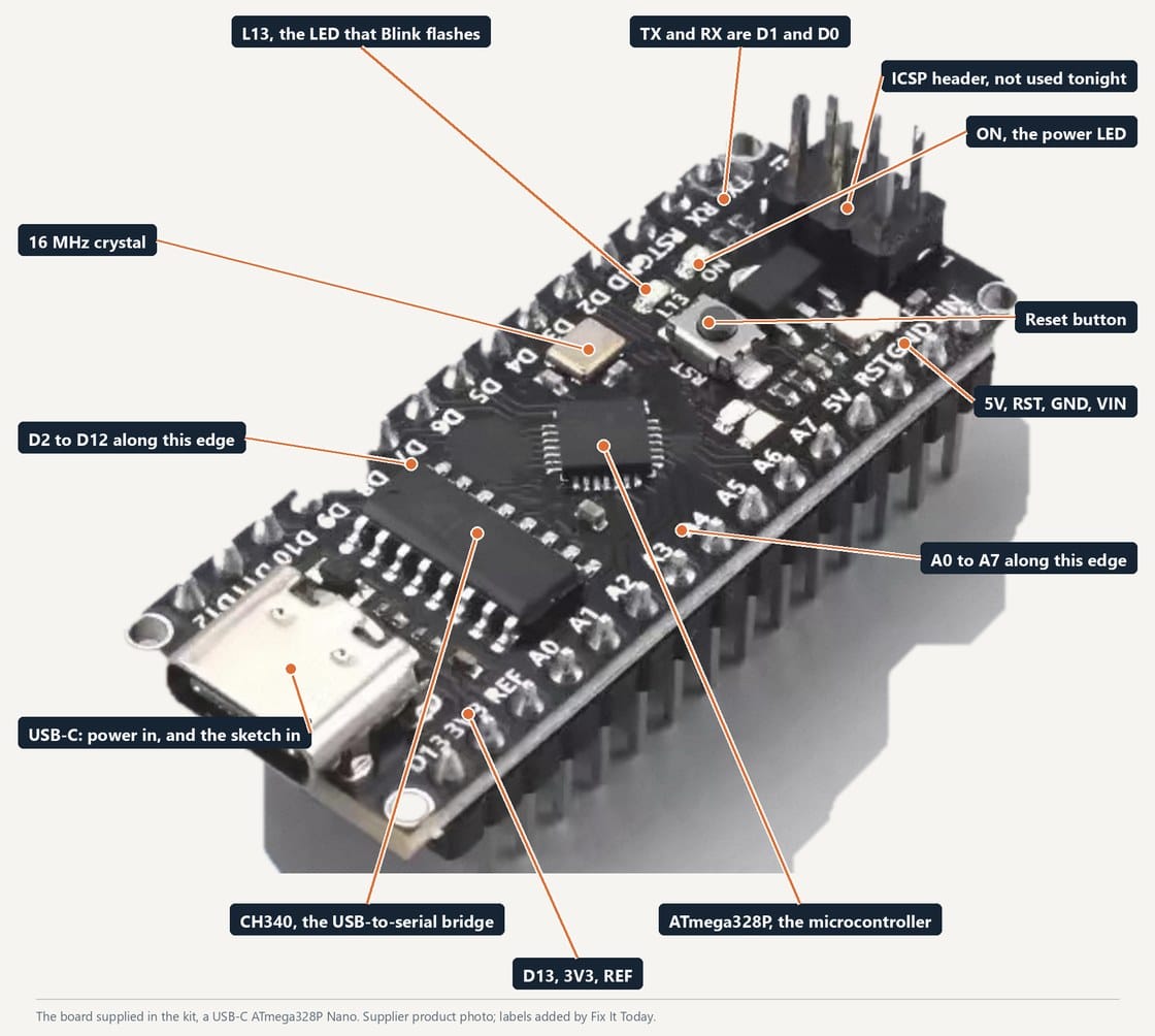
The workshop board, a USB-C ATmega328P Nano. Kit supplier's product photo, labels added by Fix It Today.
The workshop Nano, labelled
The board from the kit, with the parts you will touch marked. D2 to D12 run along one long edge, A0 to A7 along the other, and the power pins sit at the far end from the USB-C socket. Check the special functions below before choosing a pin for a module.
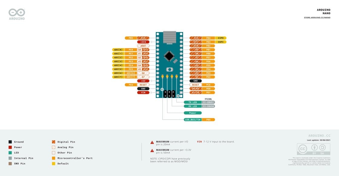
Arduino Nano pinout sheet, Arduino, CC BY-SA 4.0.
Arduino's own Nano pinout sheet
This official sheet describes the classic Nano with an FT232RL USB bridge. Use it for ATmega328P pin functions, but check your USB-C board's own specifications for its power-supply limits and USB bridge.
These pins have additional functions or restrictions that affect how you connect modules.
A6 and A7 cannot do digitalThere is no digital hardware behind them. pinMode(A6, OUTPUT) compiles cleanly, warns about nothing, and does nothing. A0 to A5 are proper digital pins as well as analog inputs.
D0 and D1 belong to the USB portPut a module on either one and it fights the USB bridge. Uploads fail, or the serial output comes back as rubbish. Leave them alone.
D13 has an LED soldered to itHandy for Blink, awkward for anything else, because the LED loads the pin. Don't use D13 for an input that matters.
Check the 3.3 V supply ratingThe 3.3 V current rating depends on the board design. Power each module at its specified voltage; this DHT11 exercise uses 5 V.
Technical details
The reset button, and why the board restarts on its own
The small button beside the ICSP header. The shield has one too, and the USB port presses it for you more often than you do.
What reset doesIt pulls the RST pin low and the ATmega328P starts again from the top: the bootloader runs for about a second, then setup(), then loop() from the beginning. Nothing is erased. The sketch in flash is exactly what it was.
Three ways to trigger it, and a fourthThe button on the Nano, the button on the shield, which sits on the same line, or pulling the RST pin low from outside. All three do the same thing. The fourth surprises people: opening the Serial Monitor.
Why the sketch restarts when you open the Serial MonitorThe USB bridge chip is wired to RST through a small capacitor, so the moment the port opens it gives the board a reset pulse. That is how uploads work without you pressing anything, and it is why sketch 4's baseline is measured again every time you open the monitor or the plotter.
When to press itA sketch that has hung. A baseline taken while a hand was over the sensor. A millis() sketch you want back at zero. Uploads normally do not need it, but if avrdude times out on a board that worked a minute ago, press reset just as 'Uploading...' appears and it usually lands.
What you will seeThe L LED flashes while the bootloader runs, then the sketch's own output starts. In the Serial Monitor a reset shows up as a one-second gap and then the first line of setup() again.
ATmega328P limits
2 KB of SRAM. Every variable, buffer and library instance lives there. Run out and the board gives you no error at all, it just corrupts and reboots.
Text in quotes gets copied into SRAM at startup unless you wrap it in F(). That's why every sketch in the workshop writes Serial.println(F("...")).
20 mA per I/O pin. An LED with its resistor is fine. A motor or a buzzer at switch-on is not, and the symptom is the board resetting.
Technical details
The I/O expansion shield and module orientation
The shield exposes Nano signals on labelled connectors. Power routing and protection depend on the shield version.
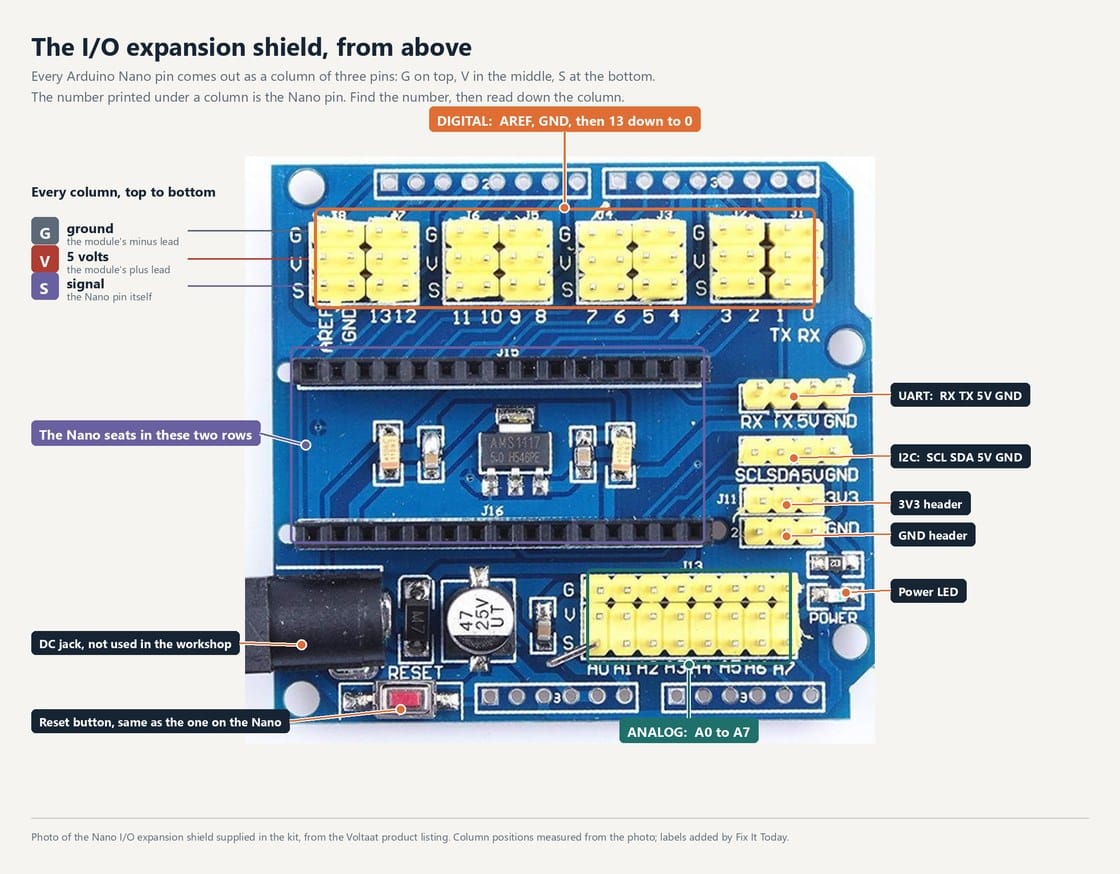
The Nano I/O expansion shield supplied in the kit, photographed from above for the Voltaat product listing. Column positions measured from the photo; labels added by Fix It Today.
The I/O expansion shield, header by header
Digital columns along the top, numbered to match the Nano, 13 down to 0, with AREF and GND at the left end. Analog columns along the bottom, A0 to A7. Every column is three pins reading G, V, S from the top. On the right, two 4-pin headers bring out the UART (RX, TX, 5V, GND) and I2C (SCL, SDA, 5V, GND), with 3V3 and GND headers below them. Bottom left: the DC jack and a reset button that does the same as the Nano's.
The Nano I/O expansion shield supplied in the kit, photographed from above for the Voltaat product listing. Column positions measured from the photo; labels added by Fix It Today.
Fit the Nano to the expansion shield
The two black rows take fifteen pins each. USB-C faces the same edge as the DC jack. Seating the board does not renumber anything: the column printed 4 is D4.
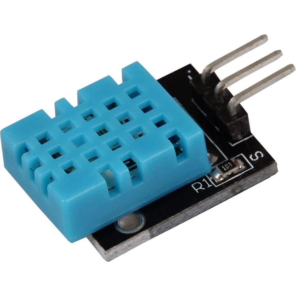
KY-015 DHT11 module, Joy-IT product photo.
Check signal, power and ground
With power disconnected, connect the KY-015 signal S to D4, VCC to 5V and minus to GND. Use separate leads when the module and shield pin orders differ. On the pictured DFRobot V1.1, check the manufacturer's servo-power selector instructions before using the VCC row.
Seating the Nano does not renumber anything. Each pin is repeated on the header printed with the same number.
Nano pinComes out atNote
D2 to D13Digital bank, column printed with the same numberOne 3-pin column each, rows G / V / S from the top
D0 and D1Digital bank, headers 0 and 1Shared with the USB serial port. Leave them free while uploading.
A0 to A7Analog bank, column printed with the same numberSame G / V / S rows as the digital bank on this board
A4 and A5Analog headers 4 and 5, and the I2C 4-pin headerThe same two pins, brought out twice. Use one or the other.
D0 and D1 againThe UART 4-pin header on the rightRX, TX, 5V, GND: the same serial pins the USB link uses
5V, GND, VIN and RSTThe power pads beside the reset button, and the DC jackNo G-V-S column of their own. USB powers everything in the workshop.
Seating the board
Putting the Nano onto the shield
Disconnect power, then check pin alignment before pressing the Nano into its sockets.
Do
Line up all thirty pins before you pressCheck that every pin aligns with a socket opening. Both ends of both rows must line up before inserting the Nano.
Match the USB end to the marked end of the shieldThe shield is printed for one orientation. Seated backwards, 5 V and GND land on the wrong pins and modules can be damaged the moment you power it.
Press down over the middle of the boardPress the board gently and evenly. Do not apply force to the USB connector.
Check that both rows are inserted evenlyThe Nano should sit parallel to the shield. Check for uneven gaps or pins that have not entered the sockets.
Upload Blink before you wire anythingBlink confirms that the Nano powers up and accepts an upload. It does not test the shield sockets or sensor connections.
Do not
Align the ends of both pin rowsShifting the Nano by one socket position connects pins to the wrong signals or supply rails. Check both ends of each row before applying power.
Do not force a bent pinStop if a pin bends or does not enter its socket. Disconnect power and ask the facilitator to inspect it.
Do not add or move modules while it is poweredUnplug the USB cable first. Hot-plugging a 3-pin lead is how a module ends up briefly reversed.
Use the module's specified supply voltageCheck both the module's voltage requirement and the board's current rating. Do not connect a 3.3 V-only module to 5 V.
Use USB power for this workshopUse the USB cable for the workshop circuit. Leave the barrel jack disconnected; external power requires checking the shield voltage and polarity specifications.
Before you plug anything in
G-V-S is common on these shields, but it isn't a standard. Plenty are printed S-V-G instead. Read the labels on your own board before you wire a whole class.
Black lead to G, red to V, signal to S. Get into the habit of connecting ground first.
The DHT11 module in this exercise uses 5 V. Other modules may require a different supply voltage.
Use USB power for this exercise. Before using a shield's barrel jack or separate servo supply, check its voltage limits, polarity and jumper arrangement in the manufacturer's manual.
Technical details
Pull-ups, contact bounce, hysteresis, timing, the ADC and PWM
The six behaviours the workshop sketches depend on.
Fix It Today workshop figure, from Reading the Air (Workshop 2, NTU MSE MIC 2026).
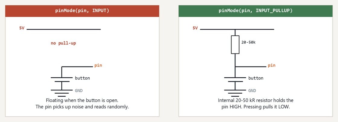
Pull-up resistors on digital inputs
A digital input left unconnected isn't low, it's undefined. INPUT_PULLUP switches on a resistor inside the chip that holds the pin high until something pulls it down.
Fix It Today workshop figure, from Reading the Air (Workshop 2, NTU MSE MIC 2026).
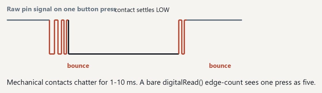
Contact bounce
A button doesn't close once. The contacts chatter for a few milliseconds, and a loop reading digitalRead() every few microseconds sees every one of those transitions as a press.
Fix It Today workshop figure, from Reading the Air (Workshop 2, NTU MSE MIC 2026).
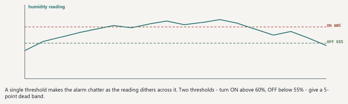
A dead band around the threshold
One threshold makes an alarm flicker on and off when the reading sits on it. Two - fire at 60 percent, clear at 55 - give the reading somewhere to sit.
Fix It Today workshop figure, from Reading the Air (Workshop 2, NTU MSE MIC 2026).
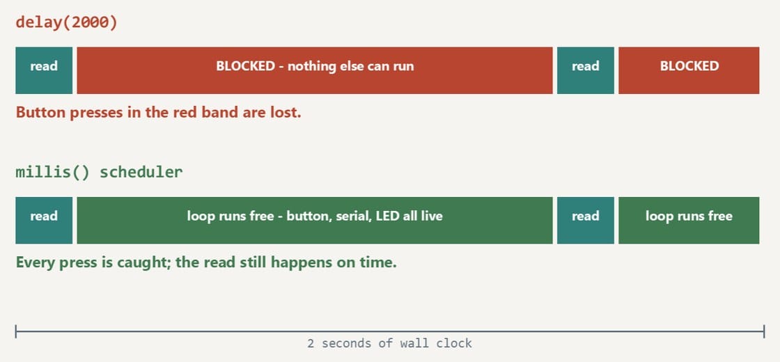
delay() against millis()
delay(2000) stops the whole sketch for two seconds, so a button press during that window is simply not seen. Checking millis() avoids a long delay between scheduled reads. The DHT11 library still blocks briefly during each sensor transaction, and its setDelay value adds a blocking wait. This is not a fully asynchronous sensor driver.
Fix It Today workshop figure, from Reading the Air (Workshop 2, NTU MSE MIC 2026).
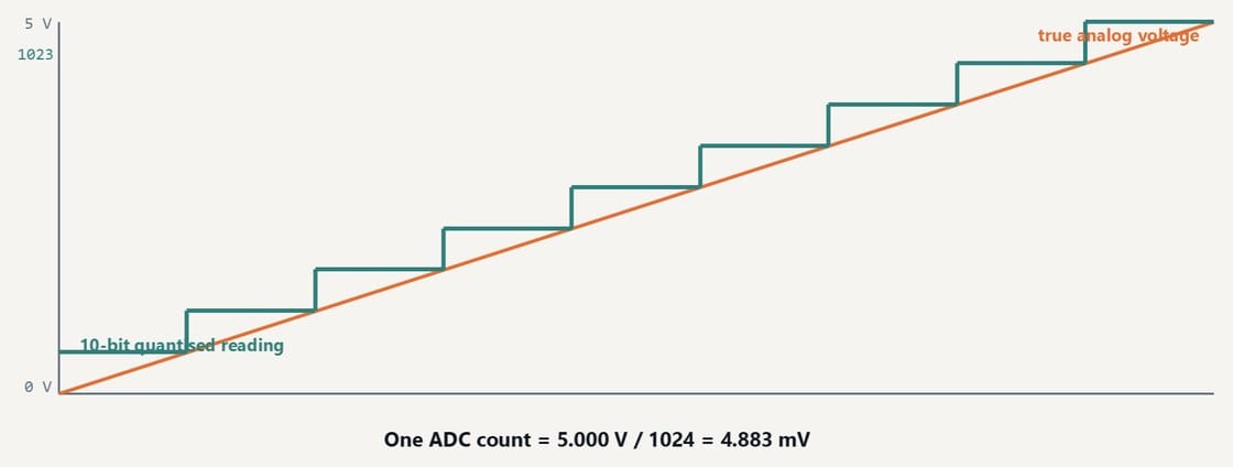
The 10-bit ADC
analogRead() returns 0 to 1023 across the reference voltage, so about 4.9 mV per step on a 5 V rail. Useful for the analog modules in the tray, and the reason a noisy analog sensor needs averaging.
Fix It Today workshop figure, from Reading the Air (Workshop 2, NTU MSE MIC 2026).
analogWrite() is PWM, not a voltage
The pin still only ever outputs 0 V or 5 V. analogWrite() changes how much of each cycle it spends high, which can dim an LED or control a suitable motor driver. It is not a true analog voltage. Use the Servo library for a hobby servo; ordinary analogWrite PWM is not the correct servo-control signal.
The Nano, shield and KY-015 pictures are the supplier and manufacturer photos of the hardware in the kit. The other photographs are Creative Commons images from Wikimedia Commons, reused under their own licences. Diagrams in the orange-and-teal house style are our own workshop figures. The kit wiring diagrams come from Keyestudio and the pinout sheet from Arduino.
USB-C Nano board photoKit supplier product photo, labels by Fix It Today, the board supplied in the kit
Nano I/O expansion shield, top viewVoltaat, supplier product photo of the kit shieldSource file
Arduino workshop benchDvlsUACh, CC BY-SA 4.0Source file
Survey and feedback
Help improve MakerAccess
Have an idea for what MakerAccess should stock, improve, or explain next? Share it in the survey. If you bought or used a product and want to comment on the item itself, use the product feedback form.