We use cookies to understand how the site is used and improve it.
Seating the Nano and Every Pin on the Shield, PWM Included
Arduino Nano shield connections and PWM
By Admin, 10/09/2026 · 14 min read
How to sit the Arduino Nano on the I/O expansion shield so every pin connects, how to check it, and what each shield pin is: ground, voltage, signal, the six PWM pins and what PWM is for, analog, serial and power.
Electronics reference
Arduino Nano shield connections and PWM
Fit the Nano to the expansion shield, check the pin alignment, then use the labelled headers to connect sensors and outputs. This guide explains power, signal, analog, serial and PWM pins.
Disconnect power before fitting the board. Align both rows of pins with the shield sockets and check the orientation shown below.
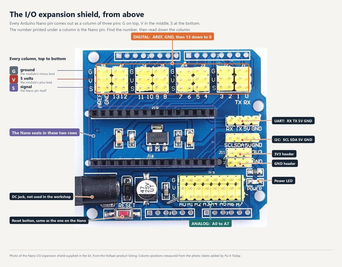
The Nano I/O expansion shield supplied in the kit, photographed from above for the Voltaat product listing. Column positions measured from the photo; labels added by Fix It Today.
Fit the Nano to the expansion shield
Disconnect power. Align all 15 pins in each row with the black sockets. The Nano USB-C connector faces the same end as the shield DC jack.
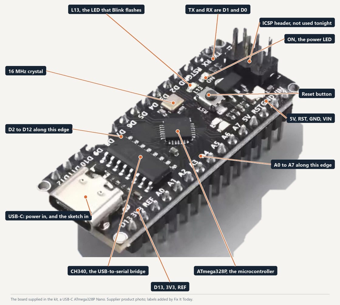
The workshop board, a USB-C ATmega328P Nano. Kit supplier's product photo, labels added by Fix It Today.
The Nano on its own, labelled
Know the two long edges before you seat it: D2 to D12 on one, A0 to A7 on the other, D13 and the power pins at the ends.
1
Disconnect the USB cable and any power supply connected to the shield.
2
For the shield shown, the Nano USB-C connector faces the same end as the DC jack. Match the pin labels on the Nano to the shield before inserting the board.
3
Align all 30 pins with the socket openings before pressing. Check both ends of each row so the Nano is not shifted by one position.
4
Press the board gently and evenly into both sockets. Do not press on the USB connector or force a pin that is not aligned.
5
Check from the side that the Nano sits parallel to the shield and both rows are inserted evenly.
6
Connect USB and upload Blink to check that the Nano powers up and accepts an upload. This does not test every shield connection. Disconnect USB before connecting the sensor.
Board levelBoth rows should be inserted evenly, with the Nano parallel to the shield.
All pins insertedCheck that no pin is bent, outside a socket or folded beneath the board.
Correct orientationMatch the Nano and shield pin labels before connecting power. Reversed connections can damage the board or sensor.
Upload checkBlink checks the Nano and USB upload. It does not confirm that every pin is connected to the shield.
Technical details
Three pins per column: G, V and S
With the Nano seated, every one of its pins is repeated on the shield as a column of three.
The Nano I/O expansion shield supplied in the kit, photographed from above for the Voltaat product listing. Column positions measured from the photo; labels added by Fix It Today.
The shield, header by header
Digital columns along the top numbered 13 down to 0, analog A0 to A7 along the bottom, the Nano sockets in the middle, UART and I2C headers on the right, DC jack and reset at the bottom left. Every column is three pins, reading G, V, S from the top.
G is ground0 V, the reference every other voltage is measured against. All the G pins on the shield are one node, joined to the Nano's GND pins and to the USB cable's ground. The black lead of a module goes here, and it goes in first, because a module with power and no ground has nowhere for current to return.
V is the supply5 V, taken from the USB cable through the Nano's 5V pin, then along a track to every V pin on the shield. It powers the module. It is not a signal and it does not change. Do not confuse it with the Nano's 3V3 pin, which comes off the USB chip and can only supply tens of milliamps.
S is the signalThe Nano pin itself. On the column printed 4, S is D4, with nothing in between: no resistor, no buffer, no protection. Whatever the module puts on S, the chip sees; whatever the chip writes to D4, the module sees. That is what makes it useful and what makes a reversed module dangerous.
Why three pinsAlmost every sensor module needs exactly these three: power, ground, one wire of information. Bundling them into one connector means one lead per module instead of three loose jumpers, and it makes the wiring rule short enough to remember: black to G, red to V, signal to S, read the letters.
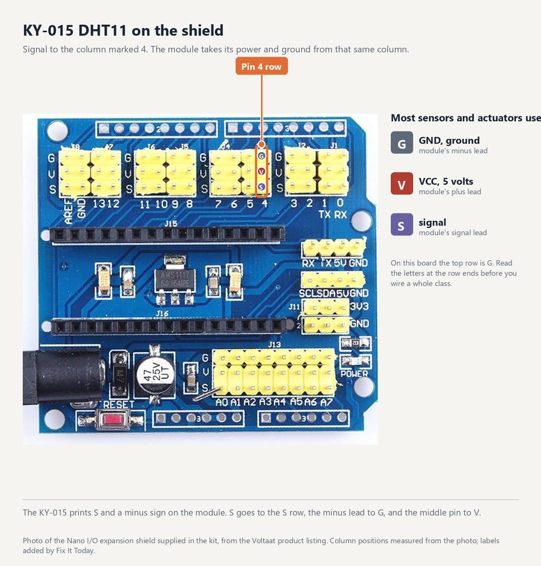
The Nano I/O expansion shield supplied in the kit, photographed from above for the Voltaat product listing. Column positions measured from the photo; labels added by Fix It Today.
One column, one module: the DHT11 on D4
Signal to the column printed 4, and the module's power and ground from the V and G rows of that same column. Every module in the kit works this way; only the column number changes.
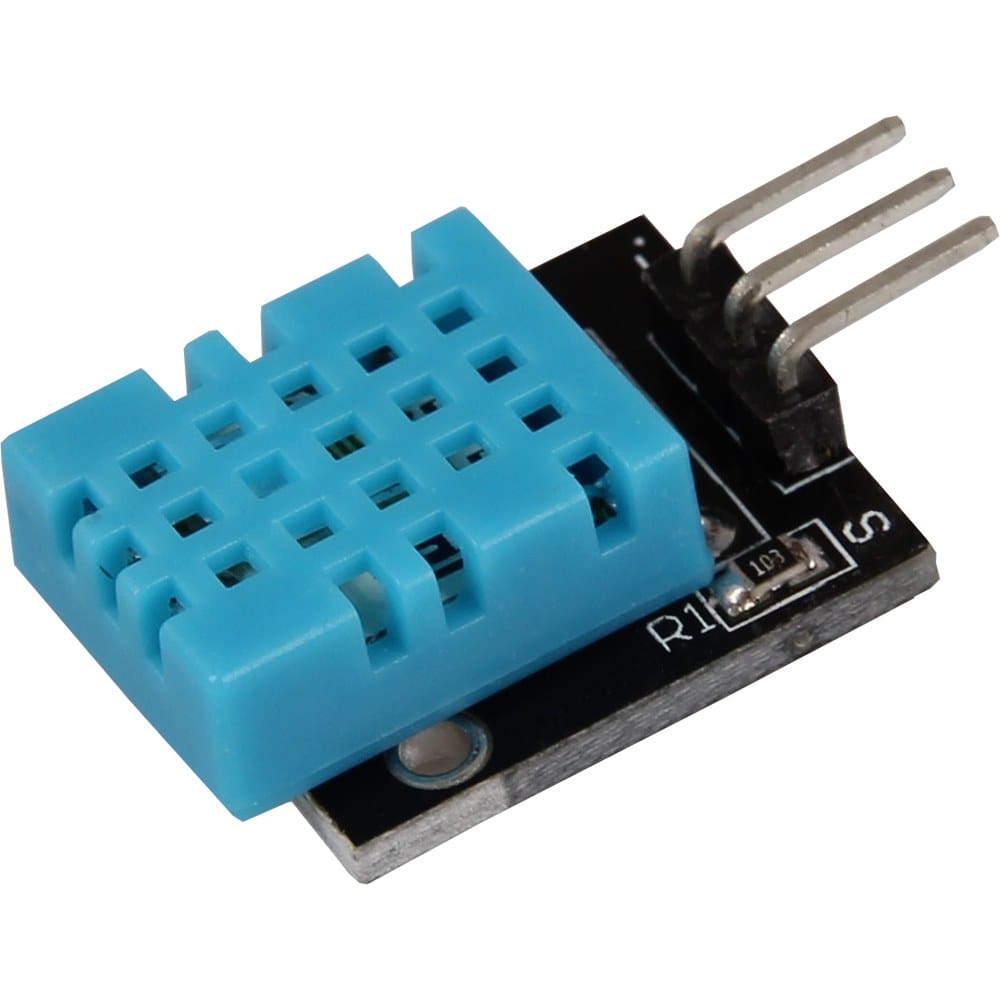
KY-015 DHT11 module, Joy-IT product photo.
A module has the same three pins
S, the middle pin for power, and minus, printed on the KY-015. Match letter to letter and it cannot go in backwards.
D0 to D13, digitalEach one is an input or an output, whichever you tell it in setup() with pinMode(). As an output it is either 0 V or 5 V, HIGH or LOW, nothing in between, up to 20 mA. As an input it reads whichever of those it sees.
D0 and D1 are the serial portTX and RX, wired to the CH340 and out through the USB cable. The Serial Monitor uses them, and so does every upload. Put a module on them and uploads fail. Leave them free.
D13 has the L LED on itHandy for Blink, and it is why Blink needs no wiring. Awkward as an input, because the LED loads the pin.
D2 and D3 can wake the chipThey are the two external-interrupt pins, INT0 and INT1: the chip can react to an edge on them without loop() polling. Not used tonight, but it is why the button station uses D2.
Technical details
The PWM pins, and what PWM is for
Six of the digital pins can fake an in-between level. Marked with a tilde: 3, 5, 6, 9, 10, 11.
Fix It Today workshop figure, from Reading the Air (Workshop 2, NTU MSE MIC 2026).
analogWrite() is PWM, not a voltage
The pin is only ever 0 V or 5 V. What changes is how much of each cycle it spends high, and that is what an LED, a motor or a servo responds to.
What PWM isPulse-width modulation. The pin is still only ever 0 V or 5 V, but the chip switches it on and off about 490 times a second and you choose what fraction of each cycle is on. analogWrite(pin, 64) is on a quarter of the time, 128 is half, 255 is always on.
What it is forAnything that responds to the average rather than the instant. An LED dims because your eye averages the flicker. A DC motor runs slower because its winding averages the current. A servo reads the pulse width as an angle. A fan speed, a heater duty, the brightness of a display backlight: all PWM.
Why only six pinsThe ATmega328P has three hardware timers and each drives two pins. That gives D3, D5, D6, D9, D10 and D11, marked with a tilde on the Nano's pinout. analogWrite() on any other digital pin quietly gives you full on or full off.
What it is notA real voltage. A meter on the pin reads the average and looks convincing, but anything that wants a steady 2.5 V, such as an analog input on another board, needs a filter or a proper DAC. The Nano has no DAC.
Workshop connectionsThe RGB LED at S1 sits on D8 and D9, and the buzzer at S3 on D5. D5 is a PWM pin, so a later sketch can soften the buzzer or pulse it instead of switching it on hard.
pwm_breathe.inoArduino C++
1// PWM: the LED on D9 breathes. Nothing else wired: KY-016 red leg on the column marked 9.
2const uint8_t LED = 9; // one of the six PWM pins: 3, 5, 6, 9, 10, 11
3
4void setup() {
5 pinMode(LED, OUTPUT);
6}
7
8void loop() {
9 for (int level = 0; level <= 255; level += 5) { // 0 = off, 255 = full on
analogWrite() takes 0 to 255. Move the LED lead to column 8, which has no timer behind it, and the same sketch gives you on or off with nothing in between.
Technical details
The analog pins, A0 to A7
A voltage in, a number out.
Fix It Today workshop figure, from Reading the Air (Workshop 2, NTU MSE MIC 2026).
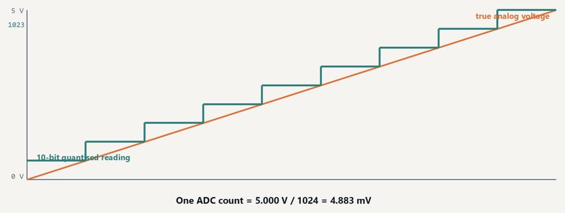
The 10-bit ADC
0 to 1023 across 0 to 5 V, so one count is about 4.9 mV.
A0 to A7 read a voltageanalogRead() returns 0 for 0 V and 1023 for 5 V, in steps of about 4.9 mV. That is a 10-bit converter, and it is what the photocell, the soil probe and the potentiometer modules talk to.
A0 to A5 are digital tooThey double as digital pins, so a kit with more switches than digital headers can put a button on A0 with pinMode(A0, INPUT_PULLUP).
A6 and A7 are input onlyThere is no digital hardware behind them. pinMode(A6, OUTPUT) compiles, warns about nothing, and does nothing. Use them for sensors, never for LEDs.
A4 and A5 are also I2CSDA and SCL. The shield's 4-pin I2C header brings out the same two pins, so an OLED on the I2C header and a sensor on A4 would fight. Use one or the other.
read_a0.inoArduino C++
1// analogRead: print the voltage on A0 ten times a second.
2const uint8_t PIN = A0;
3
4void setup() {
5 Serial.begin(9600);
6}
7
8void loop() {
9 int raw = analogRead(PIN); // 0 to 1023
10 float volts = raw * 5.0 / 1023.0; // about 4.9 mV per step
Open the Serial Plotter and turn the potentiometer module, or shade the photocell. The label:value format is what the plotter reads.
Technical details
The serial pins and the two 4-pin headers
How the board talks: to the laptop, and to other boards.
The USB serial linkSerial.begin(9600) in setup(), then Serial.print() sends text out through D1, the CH340 and the cable to the Serial Monitor. 9600 is the speed in bits per second; both ends must agree, which is the drop-down at the bottom of the monitor.
The UART headerRX, TX, 5V, GND on a 4-pin header at the right of the shield. The same two pins, brought out for a module such as a Bluetooth or GPS board. While a USB cable is in, that module and the laptop share the line.
The I2C headerSCL, SDA, 5V, GND. A two-wire bus that carries addressed messages, so several devices can hang off the same two pins: the OLED display in the kit uses it. Same pins as A4 and A5.
Technical details
The power pins
Check the voltage and current rating before powering a module.
5VFrom the USB cable, through the Nano, to every V pin on the shield. About 500 mA is available from a laptop port, and the modules in the kit take a few milliamps each.
3V3Made by the CH340 USB chip for its own use. Tens of milliamps at most. Not a supply for modules.
VIN and the DC jack7 to 12 V in, dropped to 5 V by the Nano's own regulator, which gets hot doing it. The shield's jack feeds the same place. Not used in the workshop: USB powers everything.
GNDAll of them are the same node. If a module misbehaves, the first thing to check is that its ground is actually connected.
Workshop connections
Which column each module goes on
ModuleShield column
KY-015 DHT11Digital column 4, S to D4
KY-016 RGB LEDDigital columns 8 and 9; D9 is a PWM pin, so it can dim
KY-012 buzzerDigital column 5, a PWM pin
KY-004 buttonDigital column 2, INT0, read with INPUT_PULLUP
Photocell, soil probe, vibration discAnalog columns A0 and A1
SSD1306 OLEDThe I2C header, or A4 and A5
Anything on D0 or D1Nothing, while the USB cable is in
The Nano, shield and KY-015 pictures are the supplier and manufacturer photos of the hardware in the kit. The other photographs are Creative Commons images from Wikimedia Commons, reused under their own licences. Diagrams in the orange-and-teal house style are our own workshop figures. The kit wiring diagrams come from Keyestudio and the pinout sheet from Arduino.
USB-C Nano board photoKit supplier product photo, labels by Fix It Today, the board supplied in the kit
Nano I/O expansion shield, top viewVoltaat, supplier product photo of the kit shieldSource file
Nano seated in the shieldFix It Today, store photo of the kit
Have an idea for what MakerAccess should stock, improve, or explain next? Share it in the survey. If you bought or used a product and want to comment on the item itself, use the product feedback form.