Microcontrollers, computers and PLCs
By Admin, 10/09/2026 · 10 min read

A microcontroller, a single-board computer and a PLC can all read inputs and control outputs. They differ in how they run programs, connect to equipment and handle the work they are designed for.
What is a microcontroller?
A microcontroller is a chip that contains a processor, memory and connections for inputs and outputs. It can read a sensor, check a condition and switch an output without running a desktop operating system.

How the Arduino Nano fits in
The Nano is a microcontroller board, rather than just the chip. It adds a USB connection, power circuitry, a reset button and accessible pins. The ATmega328P-based Nano used in these lessons runs the sketch uploaded from Arduino IDE.
Example: read a DHT11 sensor and turn on an LED when the temperature reaches a chosen value. A motor or other higher-power load needs a suitable driver; it must not be powered directly from a signal pin.
What is a single-board computer?
A single-board computer, such as a Raspberry Pi, has the main parts of a computer on one circuit board. It can run an operating system, manage files and run several applications.
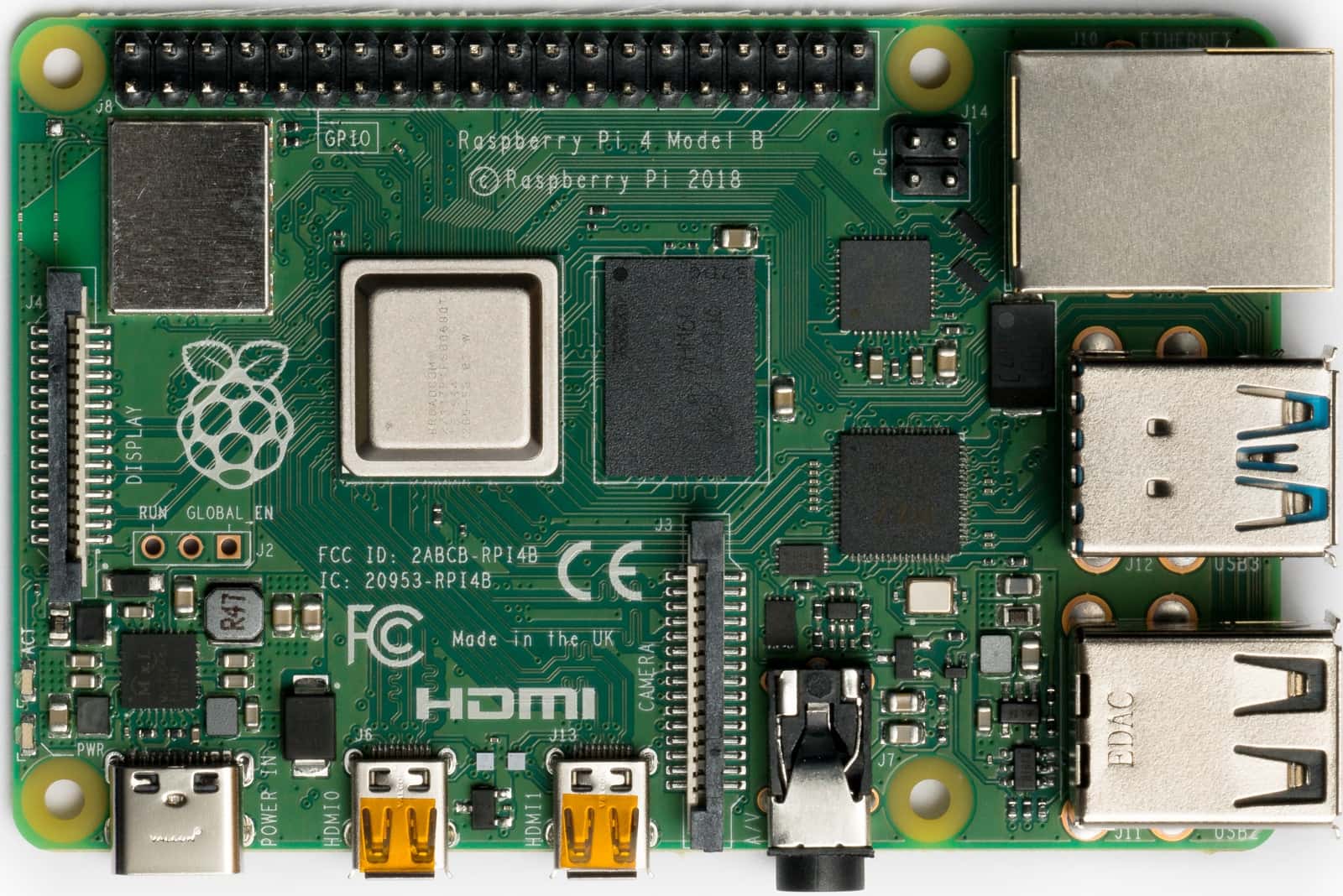
Example: log temperature readings, show a dashboard and send data over a network. A Pi and a Nano can also work together: the Nano reads the sensor while the Pi stores or displays the readings.
The Pi's GPIO signals use 3.3 V. Do not connect a 5 V output from a Nano directly to a Pi input; use an appropriate level shifter.
What is a PLC?
A programmable logic controller (PLC) is a controller designed for industrial equipment. It connects to sensors, switches and output devices through specified input/output terminals or modules.

Example: a sensor detects a container on a conveyor. The PLC checks the programmed conditions and commands a motor drive or valve. The PLC is part of the control system, not a direct replacement for every power or safety device.
How the program repeats
In a typical cyclic program, the PLC updates input values, executes its logic and updates outputs. This repeats while the controller is running. The exact order, timing and interrupt behaviour depend on the controller and its configuration.
PLC software may use ladder logic, function blocks or structured text. These express the control rules; the supported languages depend on the programming software and controller.
Which device suits the task?
| Device | Typical use | Main consideration |
|---|---|---|
| Arduino Nano | Read sensors, control LEDs and run a small embedded project. | Limited memory. Check pin voltage and use drivers for larger loads. |
| Raspberry Pi | Store data, run a dashboard, process images or provide network services. | Needs an operating system and suitable storage and power. |
| PLC | Control industrial machines and connect to industrial I/O. | Select the correct I/O modules, ratings and programming tools. |
There is no single timing or price figure for each category. Performance depends on the hardware, program and connected equipment.
Where does the Nano store a sketch?
The ATmega328P has three types of memory. Their names describe different jobs:
| Memory | Purpose | After power is removed |
|---|---|---|
| Flash, 32 KB | Stores the compiled sketch. Some space is reserved for the bootloader used during USB uploads. | The program remains stored. |
| SRAM, 2 KB | Holds working data, such as variables and sensor readings. | Working data is lost. |
| EEPROM, 1 KB | Stores values that the sketch explicitly saves, such as a calibration setting. | Saved values remain stored. |
Upload and reset
- Arduino IDE compiles the sketch into instructions for the selected board.
- During a normal USB upload, the bootloader receives the program and writes it to flash.
- The Nano restarts and runs the uploaded program.
Reset starts the existing program again; it does not erase the sketch. Disconnecting USB also leaves the sketch in flash, but the board still needs power to run.
void setup() {
  // Initialise pins and other settings once after a reset.
}

void loop() {
  // Read inputs and update outputs repeatedly.
}
For the DHT11 project, setup() starts serial communication. loop() reads the sensor and prints the results. This is similar to repeated control logic in a PLC, but it does not make the Nano an industrial controller.
What else is in a control system?
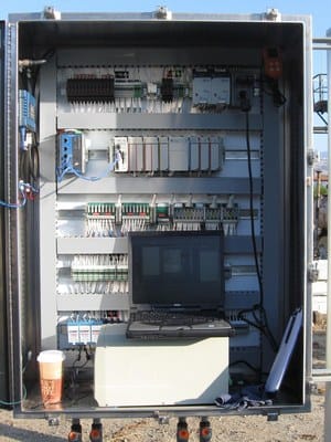
A controller decides what should happen. Power supplies, drivers, wiring and protective devices make the complete system work. Industrial panels can contain hazardous voltages; use the low-voltage workshop kit for practice and leave industrial wiring to qualified personnel.
Sources
- Arduino Nano and Arduino memory guide.
- Raspberry Pi hardware and GPIO documentation.
- Siemens S7-1200 program execution.
Photo credits
- ATmega328P: oomlout, CC BY-SA 2.0.
- Raspberry Pi 4: Laserlicht, CC BY-SA 4.0. Also used as the cover photo.
- Siemens S7-1200: UlrichAAB, CC BY-SA 3.0.
- Control cabinet: sirdle, CC BY-SA 2.0.


Related articles

Arduino Nano shield connections and PWM
How to sit the Arduino Nano on the I/O expansion shield so every pin connects, how to check it, and what each shield pin is: ground, voltage, signal, the six PWM pins and what PWM is for, analog, serial and power.

Inside the DHT11: Protocol, Frame and Accuracy
What the DHT11 is doing on its single data line, how a bit is encoded in a pulse width, how the 40-bit frame is checksummed, and what plus or minus 2 degrees C means for a project.

Arduino Nano and I/O Expansion Shield Wiring
The Arduino Nano pin map, the four pins that behave differently, how the I/O expansion shield's Ground-Voltage-Signal headers work, and the ideas the workshop sketches rely on.