We use cookies to understand how the site is used and improve it.
Arduino Nano and DHT11 Electronics Workshop
Arduino Nano and DHT11 Electronics Workshop
By Admin, 03/09/2026 · 27 min read
A step-by-step Arduino Nano and DHT11 workshop guide: install the IDE, wire the I/O expansion shield, and work through seven steps with copy-and-paste sketches, the Serial Plotter, and a hand-warmth threshold you calibrate yourself.
Electronics workshop
Arduino Nano and DHT11 workshop
Install Arduino IDE, connect the DHT11, then work through six sketches and a threshold-setting exercise. Read temperature and humidity, plot changes, and use the built-in LED as an indicator.
A small computer that runs one program, from the moment it gets power until you unplug it.
One chip, doing one jobAn Arduino is a microcontroller on a convenient board. The chip is an ATmega328P: a processor, 32 KB of program memory and 2 KB of RAM in one package, with its pins brought straight out to the edge of the board. No operating system, no files, no screen. It runs the one program you gave it, from reset, for as long as it has power.
A sketch is that programYou write it in the Arduino IDE on your laptop and press Upload, and it travels down the USB cable into the chip's flash memory. The sketch remains stored when USB is disconnected. To run without the laptop, the board still needs a suitable power supply. Every sketch has the same two parts: setup(), which runs once at power-up, and loop(), which runs over and over.
Inputs and outputsDigital pins read or write HIGH or LOW. Analog pins read a voltage as a number from 0 to 1023. Six of the digital pins can do PWM, a fast on-off pattern that dims an LED or sets a motor speed. Two pins, D0 and D1, carry the USB serial link you use to see what the board is doing.
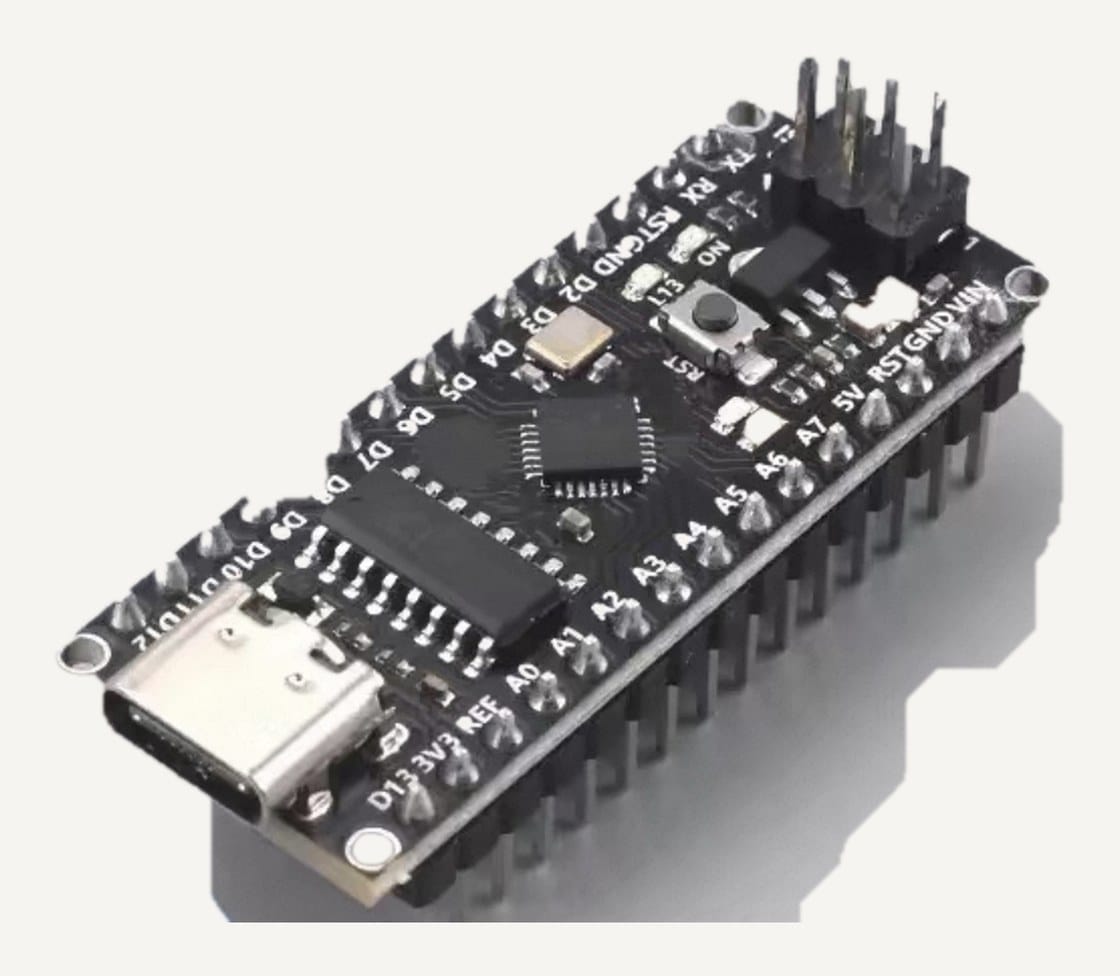
Why the Nano, and why a shieldThe Nano is the small Arduino: the same chip as the classic board, a fraction of the size, USB-C on this batch. Its pins are bare header pins, so the kit adds an expansion shield that turns every pin into a three-pin socket a sensor module plugs straight into.
The board in the kit. Small enough to sit in a breadboard, and it plugs straight into the expansion shield.
The workshop board, a USB-C ATmega328P Nano. Kit supplier's product photo, labels added by Fix It Today.
The board: a USB-C Nano
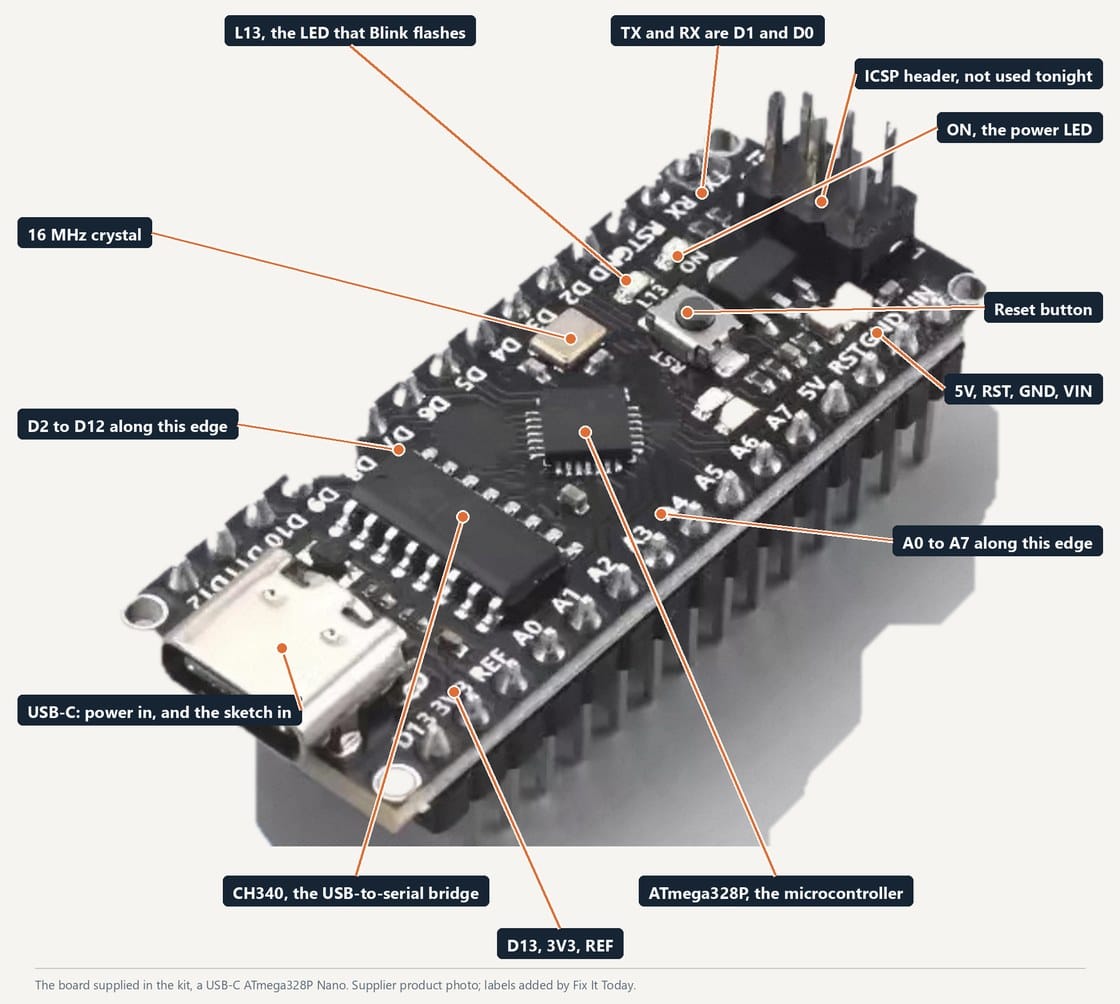
This is the board in the kit. ATmega328P in the middle, CH340 USB bridge next to the connector, reset button beside the ICSP header.
The workshop board, a USB-C ATmega328P Nano. Kit supplier's product photo, labels added by Fix It Today.
Nano pin labels
The connector, reset button and pin labels are shown below. D2 to D12 along the top edge, A0 to A7 along the bottom, power at the far end from the USB-C socket, and the reset button beside the ICSP header.
Setup
Connecting the Arduino IDE to the Arduino board
Install the software, then plug in the board and pick the right settings.
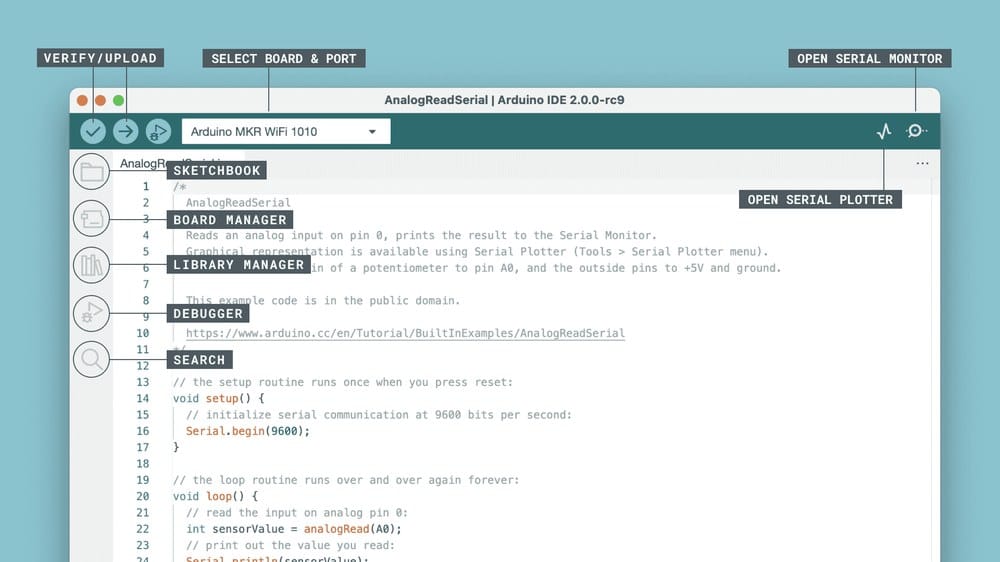
Arduino IDE 2 interface. Karl Soderby and Jacob Hylen, CC BY-SA 3.0.
Step 1
Install Arduino IDE 2
This guide is written for Arduino IDE 2. Install it before you plug the board in.
On Windows, download the 64-bit installer from arduino.cc and run the EXE. On macOS, pick Intel or Apple silicon to match the Mac, open the DMG and drag Arduino IDE into Applications.
The longer walkthrough, with the download page and the driver step, is on the Install Arduino IDE guide.
Open the IDE once before you plug anything in, so the first launch and any firewall prompt are out of the way.
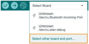
Arduino IDE board selector, from Arduino Support.
Step 2
Plug the board in and find its port
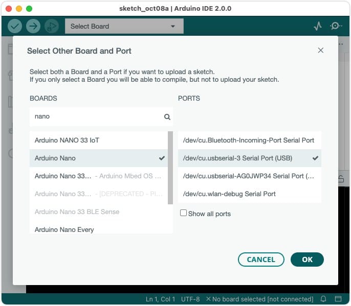
The selector beside the Upload button lists the ports the IDE can see. A CH340-based Nano may appear as Unknown, which is normal: pick Select other board and port and choose the Nano yourself in the next step.
Connect the Nano with a USB-C data cable. On Windows a new COM port appears; on macOS it shows up as a dev.usbserial or dev.wchusbserial device.
If the list stays empty, change the cable before you change anything else. That's the most common cause, and the cheapest to rule out.
If the port is missing, identify the USB bridge on your board and install its manufacturer's driver if needed. Some Windows installations already have the required driver.
Arduino IDE board and port dialog, from Arduino Support.
Step 3
Set Board, Processor and Port
Choose the board, processor and port in the Tools menu. An incorrect processor selection is one possible cause of an upload error.
Tools > Board > Arduino AVR Boards > Arduino Nano. This sets the compiler target and the pin definitions.
Tools > Processor > ATmega328P. Use ATmega328P (Old Bootloader) if the board supplier specifies it, or try that option when the cable and port are correct but uploading fails. USB-C and CH340 do not identify which bootloader is installed.
Tools > Port > the port that appeared when you connected the board. Then open File > Examples > 01.Basics > Blink and upload it as a connection test.
Upload problems, in the order to check them
The stk500_recv() error means the upload tool did not receive the expected response. Check the selected board, processor and port, then the data cable and anything connected to D0 or D1.
No port in the Tools menu at all is a cable or driver problem. A board can light up on a charge-only cable and still be invisible to the IDE.
Test one board from the workshop batch first and note its working processor setting. Use that setting for matching boards, rather than assuming every USB-C Nano has the same bootloader.
Sketch 1
Blink, before anything is wired
The Nano has an LED on D13 already. Uploading this proves the board, the cable, the driver and the IDE settings are all working.
01_blink.inoArduino C++
1// Nothing wired yet. This proves the IDE can reach the board.
2const uint8_t LED = 13; // the LED already soldered to the Nano
3
4void setup() {
5 pinMode(LED, OUTPUT);
6}
7
8void loop() {
9 digitalWrite(LED, HIGH);
10 delay(120); // <-- change this number and re-upload
11 digitalWrite(LED, LOW);
12 delay(880);
13}
Upload it, then change 120 to 500 and upload again. If the rate changes, the board, the cable, the driver and the IDE settings are all fine.
Line by line
How the Blink sketch works
The sketch sets the LED pin as an output, then switches it on and off.
const uint8_t LED = 13;Give pin 13 a name. uint8_t is a small whole number and const means it never changes. Naming the pin once at the top means the rest of the sketch reads as words, and moving the LED later is a one-line edit.
void setup() and pinMode(LED, OUTPUT);setup() runs once, when the board powers up or resets. The one thing it does here is tell the chip that pin 13 will drive something rather than listen to something. Every pin starts as an input until you say otherwise.
void loop()Everything inside loop() repeats for as long as the board has power. There is no end to reach: the last line runs and the first line starts again.
digitalWrite(LED, HIGH); delay(120);Put 5 V on the pin, which lights the LED, then wait 120 milliseconds doing nothing at all. delay() stops the whole sketch for that long. Fine here, a problem later, when the sketch has to keep watching a sensor.
digitalWrite(LED, LOW); delay(880);Pin to 0 V, LED off, wait 880 ms. 120 plus 880 is one second, so the LED gives one short flash a second. Change 120 to 500 and re-upload: a longer flash is your proof that your edit reached the chip.
The reset button
The small button beside the ICSP header. Pressing it restarts the sketch from setup(). It does not erase anything; the sketch in flash stays exactly as it was.
Opening the Serial Monitor or the Serial Plotter resets the board too, through the USB bridge. That is why the first lines print again every time you open the monitor, and why sketch 4 measures its baseline afresh.
If an upload times out on a board that was working a minute ago, press reset just as 'Uploading...' appears. The full story is on the wiring guide.
The shield
The I/O expansion shield
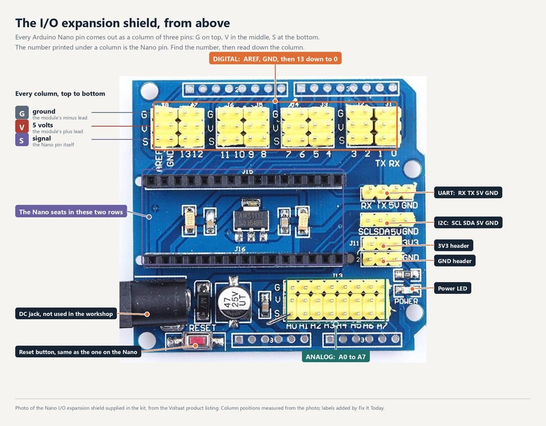
The Nano seats into the shield, and every pin comes out again as a three-pin header: ground, voltage, signal. Electrically a header pin is the Nano pin. There is nothing in between, and no protection either.
The Nano I/O expansion shield supplied in the kit, photographed from above for the Voltaat product listing. Column positions measured from the photo; labels added by Fix It Today.
Fit the Nano to the shield
Fifteen pins into each of the two black rows, USB-C at the same end as the DC jack. Seated correctly, the column printed 4 is the Nano pin D4. The four checks under the picture are the ones worth doing before the cable goes in.
The Nano I/O expansion shield supplied in the kit, photographed from above for the Voltaat product listing. Column positions measured from the photo; labels added by Fix It Today.
The shield from above: where D4 actually is
Digital columns along the top, numbered 13 down to 0; analog columns A0 to A7 along the bottom. Every column is three pins and on this board they read G, V, S from the top: minus lead to G, plus to V, signal to S. Find the digital column printed 4.
Putting the Nano on the shield
Disconnect power. Align all 30 pins with the socket openings. Check both ends of each row before pressing the board into place.
USB-C socket towards the end of the shield printed for it. Seated backwards, 5 V and GND land on the wrong pins the moment you plug in.
Press on the body of the Nano, evenly, never on the USB socket. It should sit flat with no gap under either header.
Upload Blink to check power and USB communication. Blink does not test every shield connection; check the pin alignment separately.
Wiring
One module, three pins
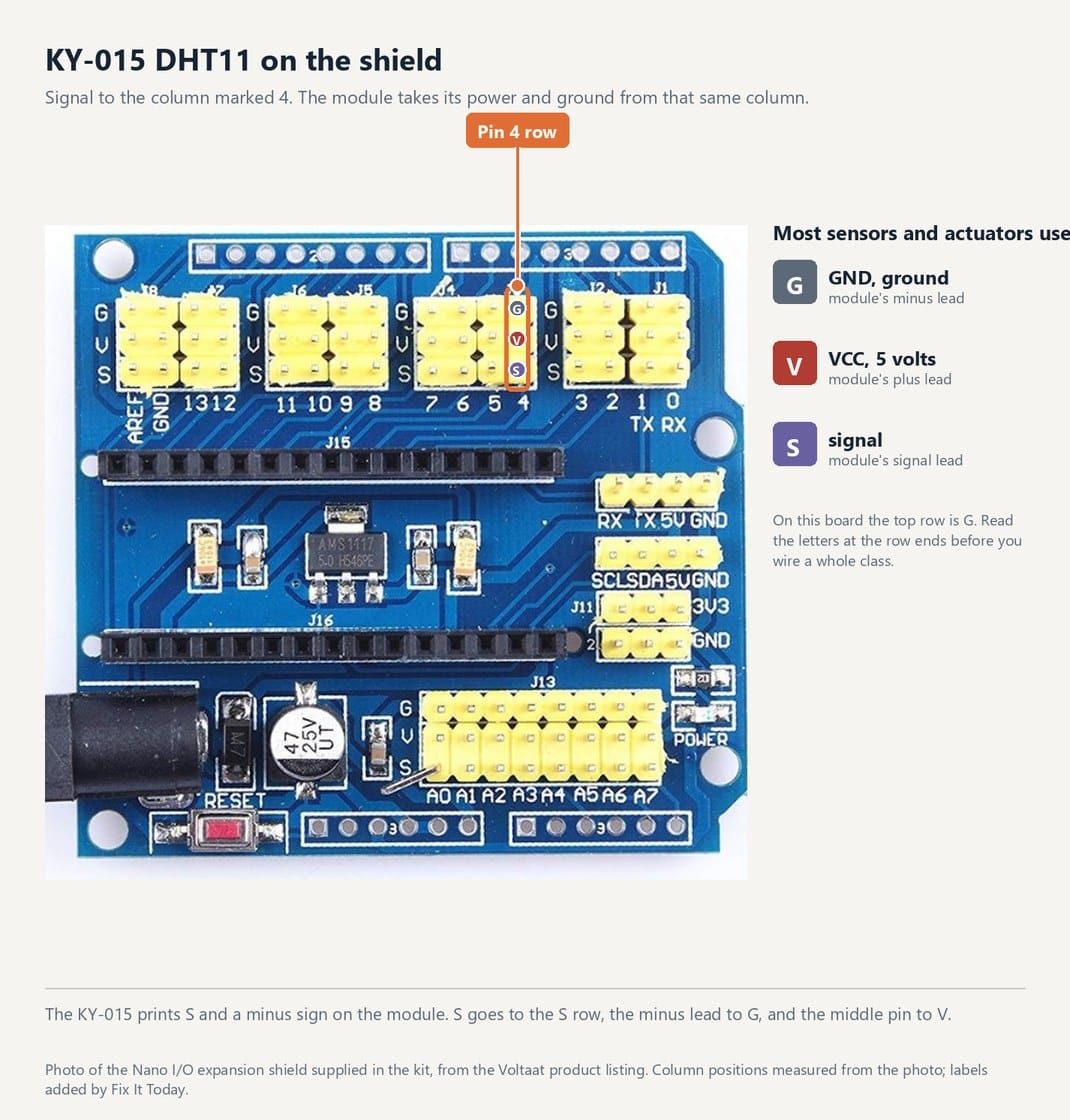
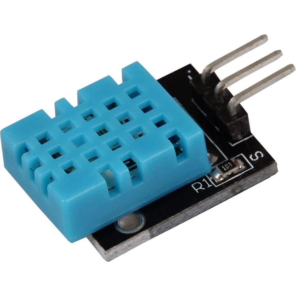
The KY-015 carries the DHT11 on a 3-pin header. Signal to D4, + to 5 V, - to GND. On the shield that is one lead into the header column marked 4 in the digital bank.
The Nano I/O expansion shield supplied in the kit, photographed from above for the Voltaat product listing. Column positions measured from the photo; labels added by Fix It Today.
Exactly where the DHT11 goes
Signal to the column printed 4 in the digital bank. The module takes its power and ground from the V and G rows of that same column, so it is one lead, not three.
KY-015 DHT11 module, Joy-IT product photo.
The KY-015 module, and which lead is which
For the pictured KY-015 module, connect S to Nano D4, VCC to 5V and minus to GND. Check your module's labels and manual: three-pin modules do not all use the same pin order. The pictured shield has a separate power selector; follow DFRobot's USB-power instructions before using its VCC row, or connect to the Nano's labelled 5V and GND pins. Leave external power disconnected for this exercise.
Minus lead to G, plus to V, signal to S. Connect ground first.
Look at the letters printed at the ends of the rows on your own shield before you plug in a whole class. G-V-S is what this batch has; other shields are printed S-V-G.
A reversed connection can damage the module. Disconnect power and match the signal, supply and ground labels before reconnecting.
Install the DHT11 library, next, before sketch 2. The sketches will not compile without it.
The library
Add the DHT11 library
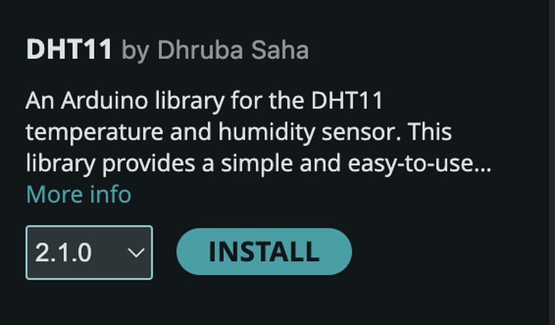
The DHT11 speaks its own single-wire protocol, so it needs a library. Install DHT11 by Dhruba Saha, 2.1.0, and nothing else.
Install DHT11 by Dhruba Saha, version 2.1.0.
The card to look for
Sketch > Include Library > Manage Libraries, search DHT11, and this is the one: DHT11 by Dhruba Saha, version 2.1.0. Not the Adafruit library of a similar name, which has a different API.
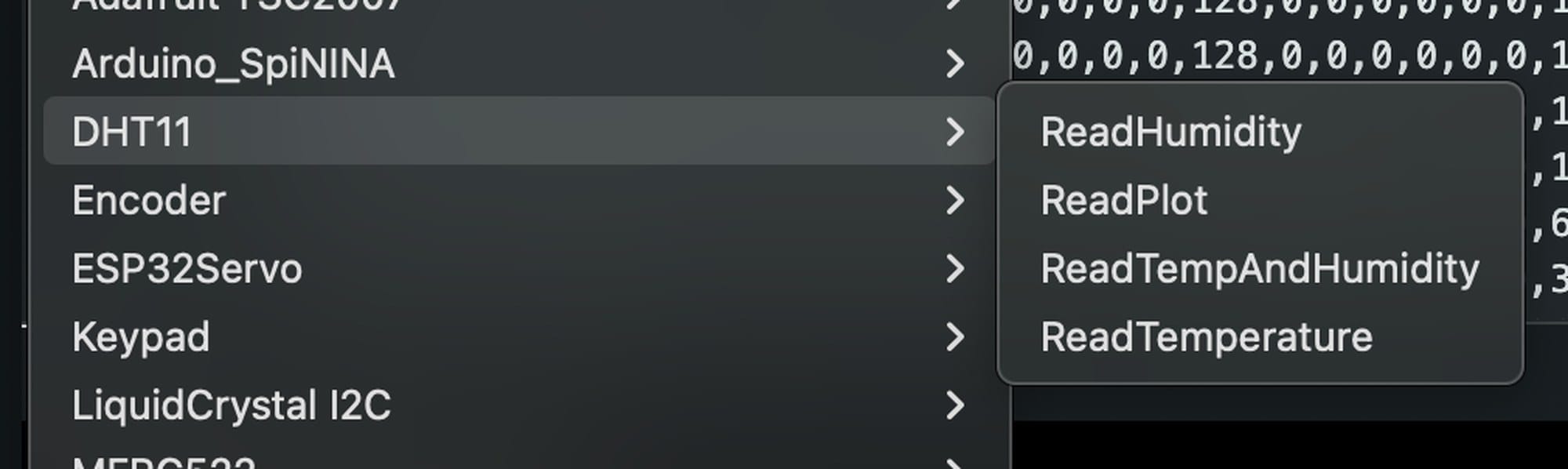
Open File > Examples > DHT11 > ReadTempAndHumidity.
Where the four examples live
Once it is installed, File > Examples > DHT11 lists ReadHumidity, ReadPlot, ReadTempAndHumidity and ReadTemperature. Start with ReadTempAndHumidity; sketch 3 below is ReadPlot with the pin changed.
Installing it
Sketch > Include Library > Manage Libraries, search DHT11, and install DHT11 by Dhruba Saha, version 2.1.0. The card should read 2.1.0 installed when it is done. Every sketch below is written for that library.
There is no second dependency to accept. If the Library Manager offers DHT sensor library by Adafruit instead, that is a different library with a different API, and these sketches will not compile against it.
After installing the library, copy the D4 example below into a new sketch. The library also includes ReadTemperature, ReadHumidity and ReadPlot under File > Examples > DHT11.
The library's own example
File > Examples > DHT11 > ReadTempAndHumidity
Copy this sketch into Arduino IDE and upload it. The sensor pin is already set to D4 to match the wiring in this guide. Open Serial Monitor and select 9600 baud.
ReadTempAndHumidity.inoArduino C++
1/**
2 * DHT11 Sensor Reader
3 * This sketch reads temperature and humidity data from the DHT11 sensor and
4 * prints the values to the serial port. It also handles potential error states
5 * that might occur during reading.
6 *
7 * Author: Dhruba Saha
8 * Version: 2.1.0
9 * License: MIT
10 */
11
12// Include the DHT11 library for interfacing with the sensor.
13#include <DHT11.h>
14
15// Create an instance of the DHT11 class.
16// Connect the DHT11 signal lead to shield S on digital column 4 (Nano D4).
17DHT11 dht11(4);
18
19void setup() {
20 // Initialize serial communication to allow debugging and data readout.
21 // Using a baud rate of 9600 bps.
22 Serial.begin(9600);
23
24 // Uncomment the line below to set a custom delay between sensor readings.
25 // dht11.setDelay(500); // Set this to the desired delay. Default is 500ms.
26}
27
28void loop() {
29 int temperature = 0;
30 int humidity = 0;
31
32 // Attempt to read the temperature and humidity values from the DHT11 sensor.
33 int result = dht11.readTemperatureHumidity(temperature, humidity);
34
35 // Check the results of the readings.
36 // If the reading is successful, print the temperature and humidity values.
37 // If there are errors, print the appropriate error messages.
38 if (result == 0) {
39 Serial.print("Temperature: ");
40 Serial.print(temperature);
41 Serial.print(" C\tHumidity: ");
42 Serial.print(humidity);
43 Serial.println(" %");
44 } else {
45 // Print error message based on the error code.
46 Serial.println(DHT11::getErrorString(result));
47 }
48}
Reproduced from the DHT11 library by Dhruba Saha, MIT licence. Reading it is the fastest way to see the shape of every sketch below: construct DHT11 with a pin, call readTemperatureHumidity with two ints by reference, and check the return value, where 0 means the read worked.
The sketches
Seven steps, in order
Blink was step 1. Each of the rest is a complete sketch: open a new sketch, select all, paste over it, upload.
1BlinkThe on-board LED on D13. Nothing wired, so it only tests the toolchain.
2First readingTemperature and humidity printed once every two seconds.
3Serial PlotterThe same readings drawn as a live graph instead of a list.
4Hand warmthMeasure the room, then light D13 when your hand raises the reading.
5CalibrationA procedure, not a sketch: set the threshold from what your own hand does.
6Steady outputTwo thresholds keep the LED steady when the reading is near the switching point.
7Temperature against humidityPlot both as change from the start and see which moves first.
Sketch 2
The first reading
Upload, then open Tools > Serial Monitor and set it to 9600 baud.
02_first_reading.inoArduino C++
1#include <DHT11.h>
2
3DHT11 dht11(4); // KY-015 signal -> D4
4
5void setup() {
6 Serial.begin(9600);
7 dht11.setDelay(2000); // datasheet: no faster than once every 2 s
8 Serial.println("temp_C, humidity_pct");
9}
10
11void loop() {
12 int temperature = 0;
13 int humidity = 0;
14
15 // 0 means the read worked. 253 is a timeout, 254 a bad checksum.
16 int result = dht11.readTemperatureHumidity(temperature, humidity);
17
18 if (result == 0) {
19 Serial.print(temperature);
20 Serial.print(", ");
21 Serial.println(humidity);
22 } else {
23 Serial.println(DHT11::getErrorString(result));
24 }
25} // no delay() here: the library waits for you
This is the library's own ReadTempAndHumidity example with the pin changed to 4, the datasheet delay set, and the printing trimmed to two columns. Two numbers every two seconds. readTemperatureHumidity() returns 0 when the read worked and 253 or 254 when it did not, so there is no NaN to test for. Breathe on the sensor and the humidity climbs within a few seconds; the temperature takes longer.
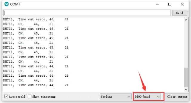
Serial output example from the Keyestudio KS0487 kit documentation.
Serial Monitor output
Two numbers every two seconds, at 9600 baud. This screenshot is from the Keyestudio kit documentation, whose sketch prints a status word before each pair; with the DHT11 library used here you get just the two numbers, and a failed read returns 253 or 254 instead of a value, which the fault table at the bottom of this page covers.
The same readings, drawn instead of listed. Tools > Serial Plotter, same 9600 baud. Close the Serial Monitor first, because only one of them can hold the port.
03_plotter.inoArduino C++
1#include <DHT11.h>
2
3DHT11 dht11(4);
4
5void setup() {
6 Serial.begin(9600);
7 dht11.setDelay(2000);
8}
9
10void loop() {
11 int temperature = 0;
12 int humidity = 0;
13 if (dht11.readTemperatureHumidity(temperature, humidity) != 0) return;
14
15 // "label:value" pairs. The plotter uses the labels as its legend.
16 Serial.print("temp_C:");
17 Serial.print(temperature);
18 Serial.print(",humidity:");
19 Serial.println(humidity);
20}
IDE 2 reads label:value pairs and builds a legend from the labels. Print anything else on the same line and the trace breaks, which is why a failed read returns early rather than printing an error. The library ships this as File > Examples > DHT11 > ReadPlot.
What to do with the plot open
Breathe across the sensor from about 10 cm. Humidity moves first and moves further. That's the water in your breath.
Cup a hand over the module without touching it and hold it there. Temperature climbs about 1 to 3 degrees over 20 to 30 seconds.
Take your hand away and time how long it takes to come back down. The plastic housing holds heat, so the fall is slower than the rise.
The trace moves in whole steps. The library returns ints because the DHT11 reports 1 degree C and 1 percent RH, so that is the sensor's own resolution showing.
Sketch 4
Hand warmth on the D13 LED
Measure the room for 20 seconds, store that as a baseline, then light the on-board LED whenever your hand pushes the reading above it. Still no extra wiring.
04_hand_warmth.inoArduino C++
1#include <DHT11.h>
2
3const uint8_t LED = 13; // the on-board LED. No extra wiring.
4const uint8_t SAMPLES = 10; // 10 readings x 2 s = 20 s of baseline
5const float RISE_C = 1.0; // <-- YOUR calibration goes here
6
7DHT11 dht11(4);
8float baseline = 0;
9
10bool bad(int v) { // one place to test both error codes
11 return v == DHT11::ERROR_TIMEOUT || v == DHT11::ERROR_CHECKSUM;
12}
13
14void setup() {
15 pinMode(LED, OUTPUT);
16 Serial.begin(9600);
17 dht11.setDelay(2000);
18
19 Serial.println("Hands off. Measuring the room.");
20 long total = 0;
21 uint8_t taken = 0;
22 while (taken < SAMPLES) {
23 int t = dht11.readTemperature();
24 if (!bad(t)) { total += t; taken++; Serial.print('.'); }
25 }
26 baseline = total / (float) SAMPLES; // ten whole readings, one fraction
27
28 Serial.println();
29 Serial.print("Room baseline ");
30 Serial.print(baseline, 1);
31 Serial.println(" C. Now cup a hand over the sensor.");
readTemperature() hands back a whole number, so averaging ten of them is what gives the baseline a decimal place to work with. RISE_C starts at 1.0, which is a guess; sketch 5 replaces it with a number you measured.
Step 5
Calibrating the threshold to your own hand
The right threshold depends on the room, the sensor, and how close you hold your hand, so measure it.
1
Upload sketch 4 and keep your hands away from the bench. Wait for the baseline line to print, about 20 seconds.
2
Cup a hand over the sensor, 1 to 2 cm above it, without touching it. Hold still and watch the rise value in the Serial Monitor.
3
Note the highest rise you can hold for ten seconds. In a normal room that's usually 1 to 3 degrees C.
4
Take your hand away and watch rise fall back towards zero. Note how long that takes; 30 to 60 seconds is normal.
5
Set RISE_C to about half your highest rise. If you held 2.0, use 1.0.
6
Re-upload and check it: the LED should come on within about 10 seconds of your hand arriving, and go off within a minute of it leaving.
If the calibration won't hold
The LED never comes on: your RISE_C is above what your hand can do. Lower it, or hold your hand closer.
The LED is on before you start: the baseline was measured with a hand or a laptop vent near the sensor. Reset the board and stand back.
The LED flickers on and off around the threshold: that's a single-threshold problem, and sketch 6 fixes it.
Everything reads whole numbers: correct. The DHT11 has 1 degree C resolution, so a rise of 1.0 is one whole step.
Sketch 6
Keep the LED steady with two thresholds
Switch on when the temperature rise reaches 1.5 degrees C and switch off below 0.5 degrees C. Between those values, keep the previous LED state. This is hysteresis. The sketch below still waits inside the DHT11 read; it does not use a millis-based scheduler.
06_steady.inoArduino C++
1#include <DHT11.h>
2
3const uint8_t LED = 13;
4const float ON_RISE = 1.5; // switch on above this
5const float OFF_RISE = 0.5; // switch off below this
6const uint8_t SAMPLES = 10;
7
8DHT11 dht11(4);
9float baseline = 0;
10bool warm = false;
11
12bool bad(int v) {
13 return v == DHT11::ERROR_TIMEOUT || v == DHT11::ERROR_CHECKSUM;
Switching on at 1.5 and off at 0.5 leaves a 1 degree gap. Widen it if the LED still flickers, narrow it if the LED stays on too long after your hand leaves. Note that the read itself blocks for the whole setDelay period, so nothing else in loop() runs during it.
Sketch 7
Temperature against humidity
Both plotted as change from the first reading, so they share one scale and you can see which one reacts first.
07_temp_vs_humidity.inoArduino C++
1#include <DHT11.h>
2
3DHT11 dht11(4);
4int t0 = -1, rh0 = -1; // the first good reading, as a reference
5
6void setup() {
7 Serial.begin(9600);
8 dht11.setDelay(2000);
9}
10
11void loop() {
12 int temperature = 0;
13 int humidity = 0;
14 if (dht11.readTemperatureHumidity(temperature, humidity) != 0) return;
15
16 if (t0 < 0) { t0 = temperature; rh0 = humidity; } // first pass only
17
18 // Both plotted as change from the start, so they share one scale.
19 Serial.print("temp_delta:");
20 Serial.print(temperature - t0);
21 Serial.print(",humidity_delta:");
22 Serial.println(humidity - rh0);
23}
Breathe on it and humidity jumps well ahead of temperature. Cup your hand over it instead and temperature leads. The two signals have different sources and different lag.
Next
Things to change
Small edits to the sketches above. Each takes a couple of minutes.
Change the sample intervalCompare dht11.setDelay(2000) with dht11.setDelay(5000). The slower setting gives fewer samples; keep at least two seconds between reads for this exercise.
Average the readingKeep the last five values in an array and print the mean. The trace gets smoother, and the fixed error stays exactly where it was.
Add a second thresholdLight D13 for a small rise and add a buzzer on D5 for a large one.
Log itPrint millis() as the first column, run for ten minutes, then paste the Serial Monitor into a spreadsheet and plot it there.
Cover the sensorPut the module in a cup and watch how long the humidity takes to settle. It runs to minutes.
Swap the sensorUse the analog temperature module's own wiring and example sketch, then compare its response with the DHT11. The DHT11 library does not read an analog module.
Faults
Troubleshooting
Work down this table before changing the sketch. Most of these are a cable, the wiring, or one menu setting.
SymptomPossible causeFix
No COM port in the Tools menuCharge-only cable, or no CH340 driverSwap the cable first. Then install the driver and replug the board.
avrdude: stk500_recv() not respondingWrong Processor settingSwitch Tools > Processor between ATmega328P (Old Bootloader) and ATmega328P, then upload again.
Every read prints a timeout errorModule in backwards, unpowered, or on the wrong pinBlack lead on G, red on V. Then check DHT11 dht11(4) matches the header it is plugged into.
The board resets when the buzzer soundsBrown-out from switch-on currentNot a software bug. Power the buzzer separately, or drop it.
Readings barely moveSampled faster than the sensor updatesdht11.setDelay(2000), which is the datasheet limit.
An LED is permanently on and the module is warmModule plugged in backwardsUnplug it now, then check the orientation before repowering.
Serial output is garbage charactersBaud rate mismatch, or something wired to D0 or D1Match the Serial Monitor to Serial.begin(9600), and keep D0 and D1 free.
pinMode(A6, OUTPUT) does nothingA6 and A7 have no digital hardware behind themUse A0 to A5 if you need a pin that can do both.
'DHT' does not name a typeThe Adafruit library is installed, not this oneInstall DHT11 by Dhruba Saha and use DHT11 dht11(4).
The rest of the kit
Explore the sensor kit
Every module in the 37-in-1 kit has its own page, with what it detects, how the sensing works and a starter sketch.
The Nano, shield and KY-015 pictures are the supplier and manufacturer photos of the hardware in the kit. The other photographs are Creative Commons images from Wikimedia Commons, reused under their own licences. Diagrams in the orange-and-teal house style are our own workshop figures. The kit wiring diagrams come from Keyestudio and the pinout sheet from Arduino.
USB-C Nano board photoKit supplier product photo, labels by Fix It Today, the board supplied in the kit
Nano I/O expansion shield, top viewVoltaat, supplier product photo of the kit shieldSource file
Arduino IDE 2 interfaceKarl Soderby and Jacob Hylen, CC BY-SA 3.0Source file
Survey and feedback
Help improve MakerAccess
Have an idea for what MakerAccess should stock, improve, or explain next? Share it in the survey. If you bought or used a product and want to comment on the item itself, use the product feedback form.