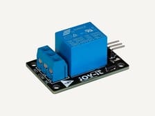
Light meter
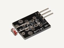
Photoresistor on A5, plotted live. Cover it, shine a torch on it, hold a sheet of paper over it.
Sensor modules
Photoresistor
What you need
37-in-1 Arduino Sensors Kit
By Fix It Today, 05/07/2026 · 9 min read

Sensor lab
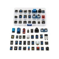
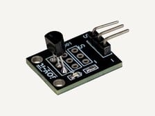
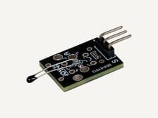
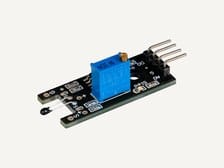
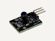
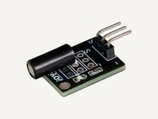
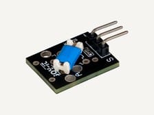
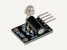
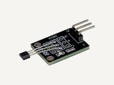
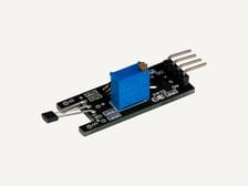
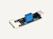
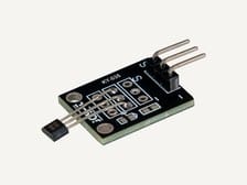
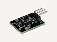
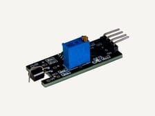
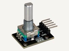
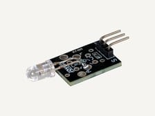
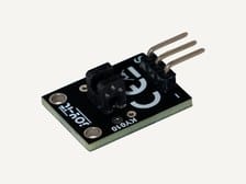
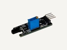
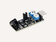
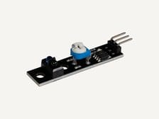
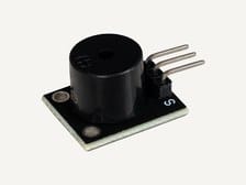
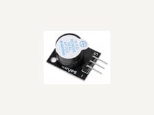
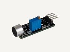
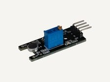
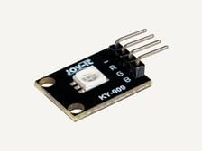
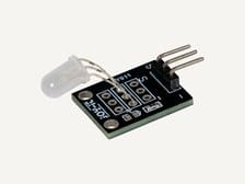
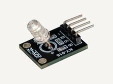
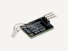
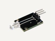
The KY-series kit: 37 modules on their own little boards, each with three or four pins that plug straight into the Nano expansion shield. Start with one module, see its value change, then build from there. The photos below are the actual modules; the boards in the box may not carry the Joy-IT print but are the same parts. alert, game, or moving project.
Start here
Install the Arduino IDE and upload Blink to the bare Nano. That proves the board, cable and settings.
Seat the Nano on the expansion shield, USB-C at the DC-jack end, all thirty pins home.
Start with the KY-004 push button (a digital input), then the KY-018 photoresistor (an analog input), then the KY-015 DHT11 (a sensor that sends data).
One module at a time. Get its reading on the Serial Monitor before you add a second one.
Power off first
Unplug the USB cable every time you change a module.
A lead plugged in live can touch the wrong pin for a moment, and 5 V on a signal pin is how a module dies. Unplug, wire, check the letters, then plug the cable back in.
Pick a direction
Choose the kind of signal first, then open a module card for details.
Starter wiring
Every module in this kit is a 3-pin header: ground, voltage, signal. On the Nano expansion shield that is one lead into the numbered header the sketch uses. Each module page lists its own pins.
Project grid
Each card starts from the listed kit modules and project components. Optional request parts are labelled only when they come from wider FIT inventory.
Photoresistor on A5, plotted live. Cover it, shine a torch on it, hold a sheet of paper over it.
Sensor modules
What you need
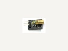
The laser across a gap onto the photoresistor. Every time something breaks the beam, count one.
Sensor modules
What you need
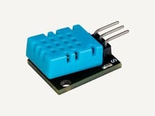
DHT11 on D4, active buzzer on D5. Beep when a breath pushes humidity over a threshold, with a dead band so it does not chatter.
Sensor modules
What you need
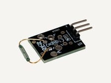
Reed switch on the frame, magnet on the door. The RGB LED shows green closed, red open.
Sensor modules
What you need
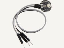
Fingertip on the heartbeat sensor, Serial Plotter open. Count the dips over fifteen seconds and multiply by four.
Sensor modules
What you need
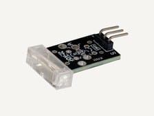
Knock sensor counts taps; three in two seconds lights the two-colour LED green, anything else red.
Sensor modules
What you need
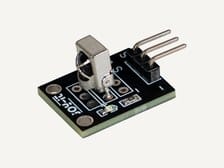
Any TV remote at the IR receiver. Each button sets a different colour on the RGB LED.
Sensor modules
What you need
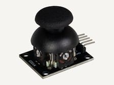
X axis sets the pitch on the passive buzzer, Y sets how long each note lasts. A one-stick instrument.
Sensor modules
What you need
All 37 modules
One page per module: what it does, how it works, exactly where it plugs in on the shield, and a sketch that compiles for the Nano.
Step-by-step guides
The workshop guides take one module all the way from an empty laptop to working code, and the wiring reference covers the board and the expansion shield.
Source links
Use these references to check the kit list, see wiring diagrams, or test code before using hardware.
Survey and feedback
Have an idea for what MakerAccess should stock, improve, or explain next? Share it in the survey. If you bought or used a product and want to comment on the item itself, use the product feedback form.
Do the surveyProduct feedback form