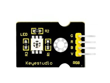
Use this source photo to identify the module before wiring it. The photo is saved from the checked 37-in-1 kit guide.
What it detects
Mixes red, green, and blue light.
This is the main signal to test before adding displays, motors, buzzers, or game logic.
How it works
This module combines red, green, and blue LEDs in one package. Code controls each colour channel separately, so changing the brightness of the three channels mixes different visible colours.
Matching the part number
This module is usually sold as KY-016. If yours is printed with that code, the vendor datasheet and the original example sketch are in the KY-numbered kit repository linked at the bottom of this page.
That repository documents a different 37-in-1 kit. The two overlap on this module, but its module list is not the same as the Keyestudio one, so check the part in front of you rather than the kit name.
What you need
Starter parts
Keep the first circuit small and add displays or motors later.
White USB Type-C CableConnects or powers USB-C devices, boards, chargers, and project accessories.
Arduino Nano & Expansion BoardCompact controller and breakout board for sensors, wiring, and embedded projects.
Female to Male 10 cm Wire10 cm Jumper Wire for connecting breadboards to male-pin modules or sensors.
37-in-1 Arduino Sensors KitExplore light, sound, motion, touch, and environmental sensing with Arduino projects.
Try first
Turn each colour channel on one at a time.
This is the quickest way to see the module reading change.
Connections
Wiring to the Arduino Nano on its expansion shield
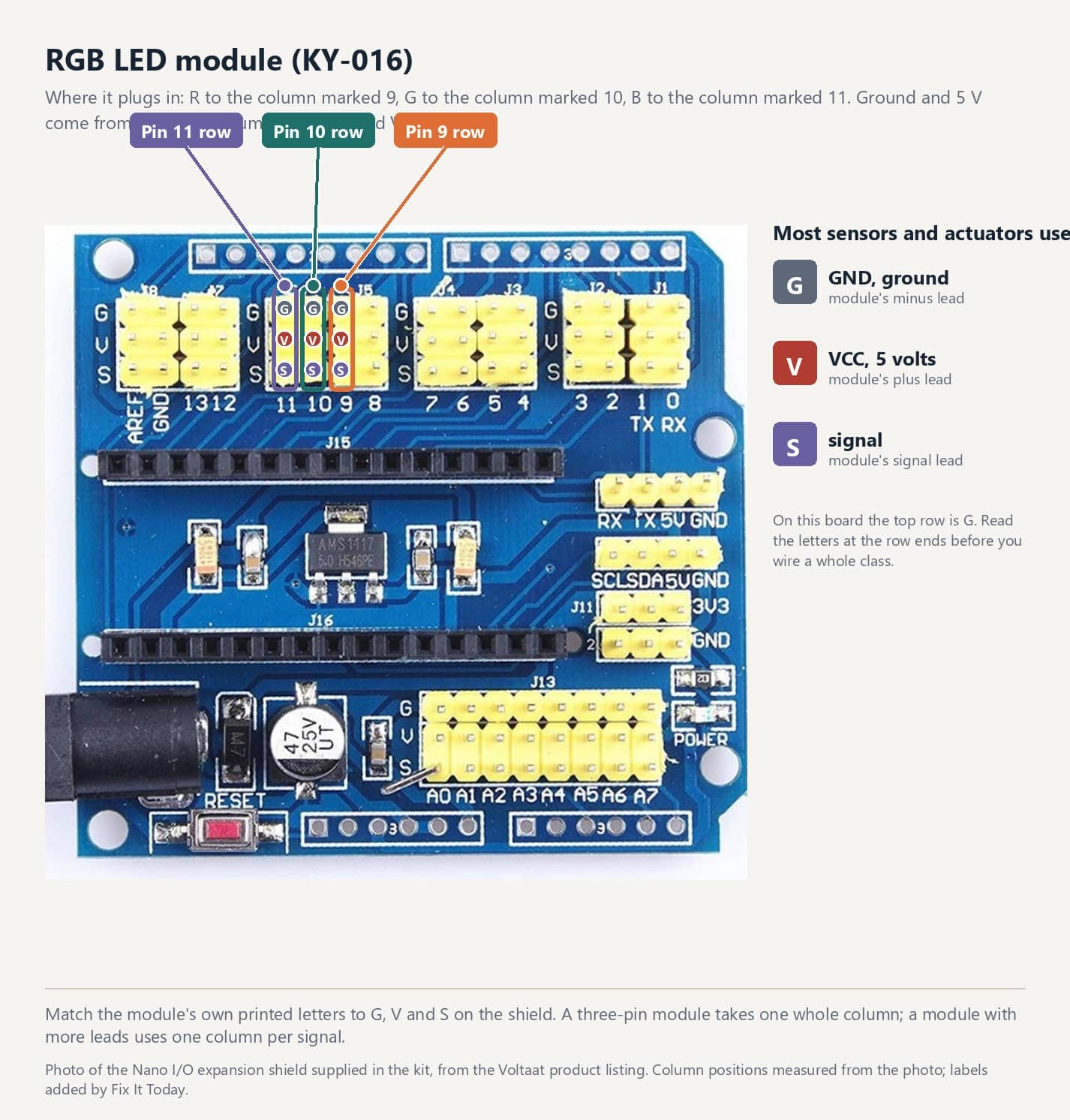
Plug into the digital bank of headers. The pin numbers below match the sketch further down this page; change one and change the other.
Module pinGoes to
Module RShield header D9
Module GShield header D10
Module BShield header D11
The Nano I/O expansion shield supplied in the kit, photographed from above for the Voltaat product listing. Column positions measured from the photo; labels added by Fix It Today.
Where it plugs in
The ringed column on the shield is the one this module uses. Its three pins are ground on top, 5 V in the middle and the signal at the bottom, so a three-pin module takes one whole column.
Before you power it
On this shield both banks read G, V, S from the top: the black lead goes to G, the red to V and the signal to S. The letters are printed at the ends of the rows, so check them on your own board before you wire a whole class.
One 3-pin lead per module. Connect ground first, then power, then signal.
A module in backwards puts 5 V on the signal pin. Some shrug it off, plenty do not.
The pin map and the shield layout are on the Nano and expansion shield wiring guide.
1
Plug the module into the header listed above, black lead to ground.
2
Copy the sketch below, upload it, and open Tools > Serial Monitor at 9600 baud.
3
Change the physical condition the module senses and watch the reading or output respond.
Starter sketch
Code you can copy and upload
Set the pin constants at the top of the sketch to match the header you plugged the module into, then upload it and open Tools > Serial Monitor at 9600 baud.
rgb_led_module.inoArduino C++
1const uint8_t R = 9, G = 10, B = 11; // all three must be PWM pins
Have an idea for what MakerAccess should stock, improve, or explain next? Share it in the survey. If you bought or used a product and want to comment on the item itself, use the product feedback form.