Thermal Simulation in Fusion
By Admin, 16/07/2026 · 3 min read
Fusion simulation
Thermal Simulation in Fusion
Set up and check a steady-state heat-transfer study using a finned heat sink as the worked example.
Study
What the model answers
A steady-state thermal study estimates temperatures after the system has settled. It does not show warm-up time. The answer depends on material conductivity, heat input, thermal contacts and how heat leaves the model.
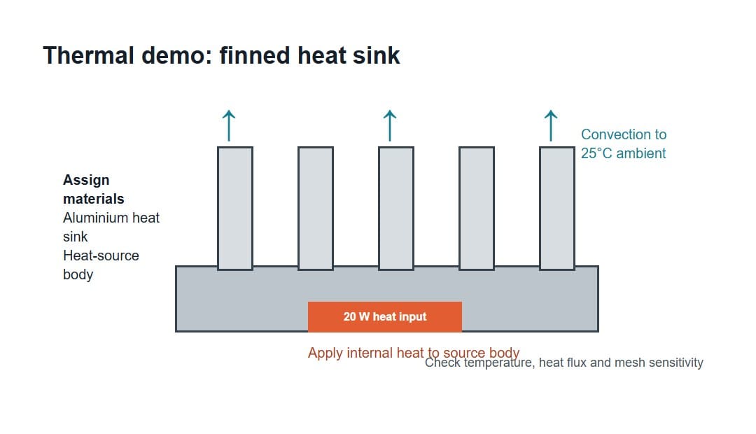
Demo settings
Tutorial
Fusion thermal simulation steps
Open each image to view the Fusion controls at full size. The Applied Temperature panel is included for models with a genuinely controlled-temperature face; the 20 W heat-sink demo instead uses Internal Heat.
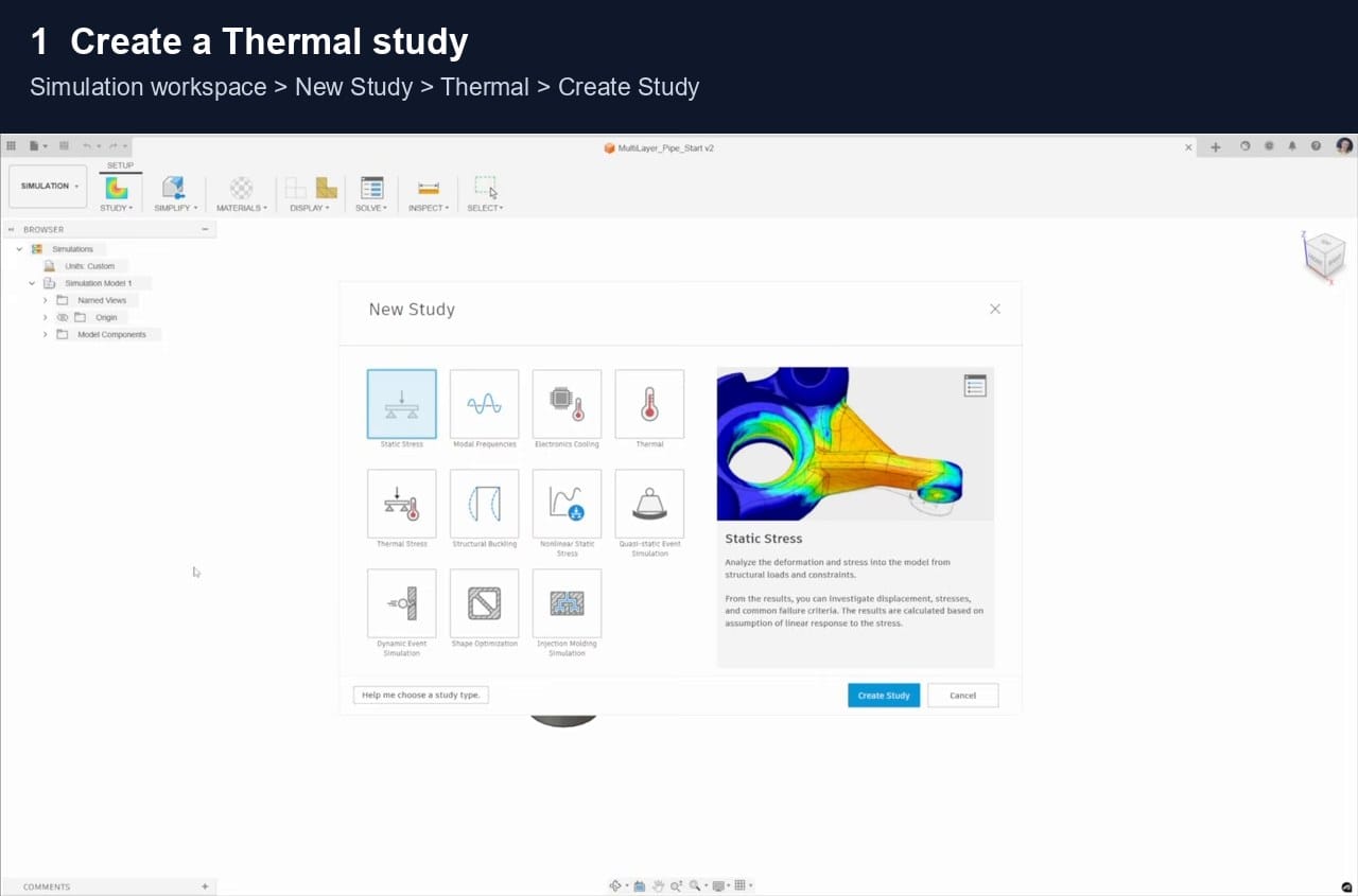
Open the model, change the workspace from Design to Simulation, then choose New Study > Thermal > Create Study. A thermal study predicts how heat moves through the model after temperatures have settled; it does not calculate how long warming takes.
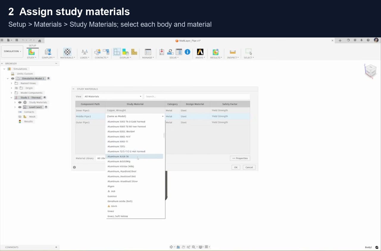
Choose Setup > Materials > Study Materials and assign each real material. Thermal conductivity describes how easily heat passes through a material: a high value spreads heat quickly, while a low value acts more like insulation. Density and specific heat mainly matter when temperature changes with time; conductivity is central to this steady-state study.
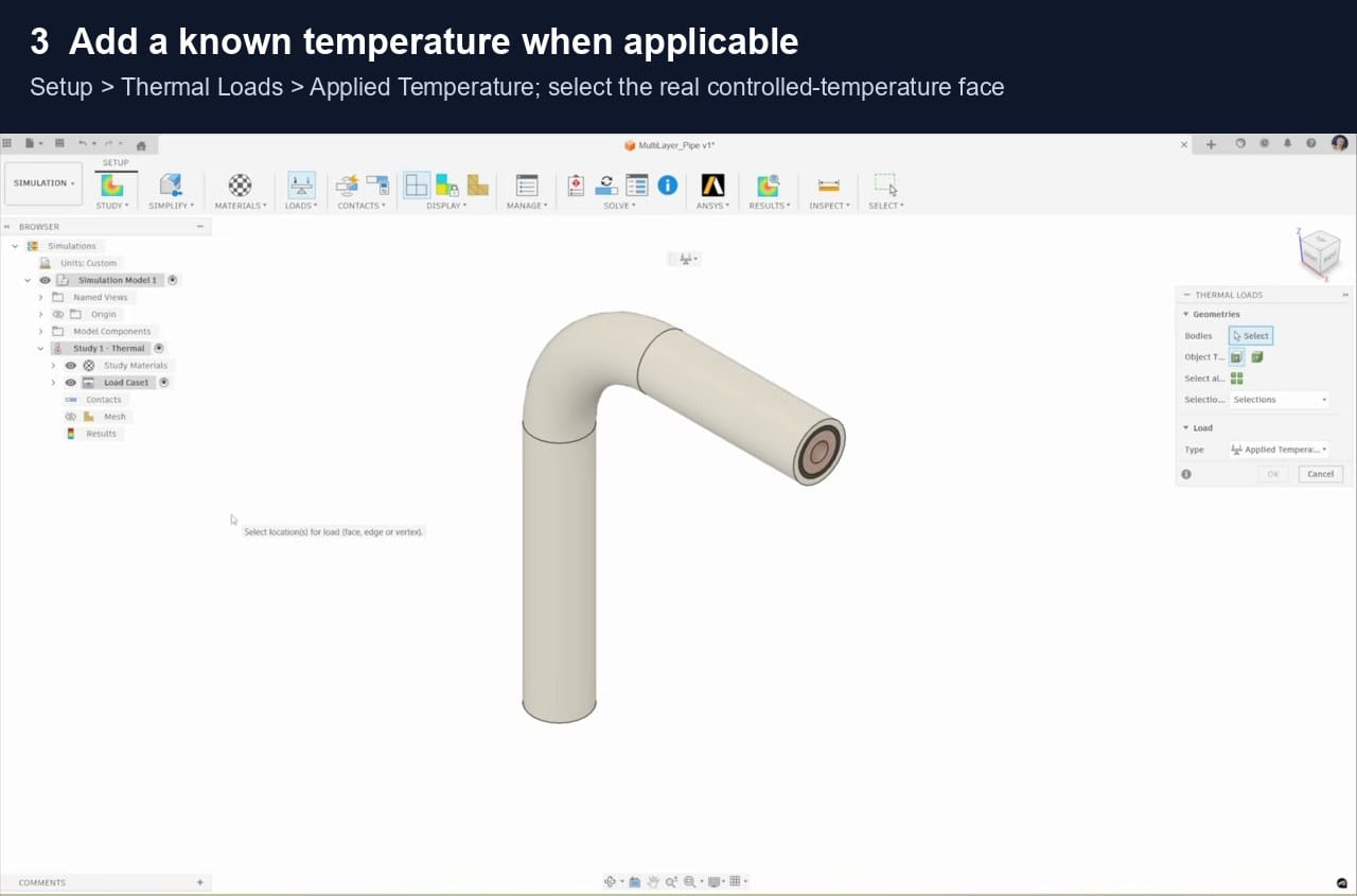
For this heat-sink demo, choose Setup > Loads > Thermal Loads > Internal Heat, select the source body and enter 20 W. A watt is one joule of energy transferred each second. Applied Temperature, shown here, should be used only when a real face is maintained at a known temperature.
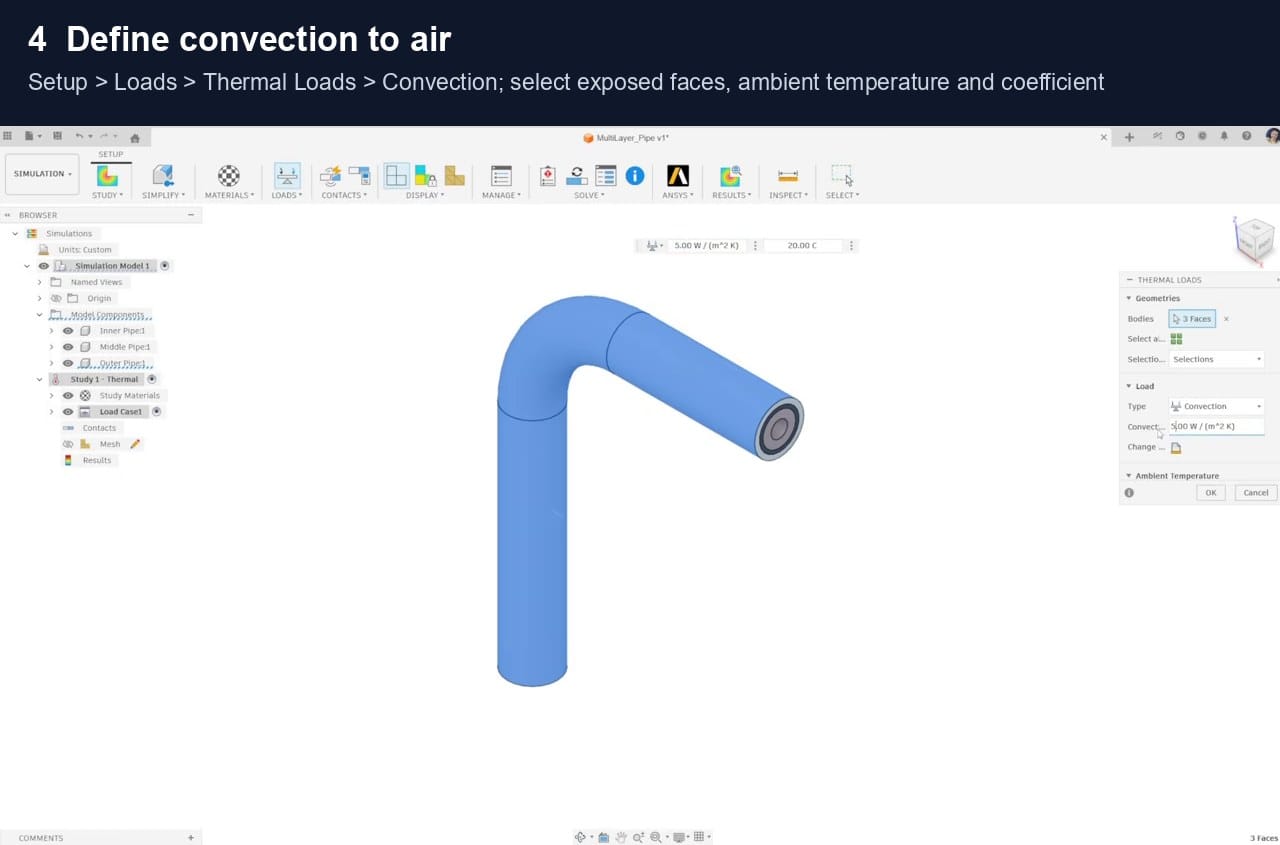
Choose Setup > Loads > Thermal Loads, set Type to Convection, and select every air-exposed surface except the source contact. Convection represents heat carried away by moving air or liquid. The heat-transfer coefficient states how strongly that fluid removes heat, so use a value that matches natural airflow, forced airflow or liquid cooling.
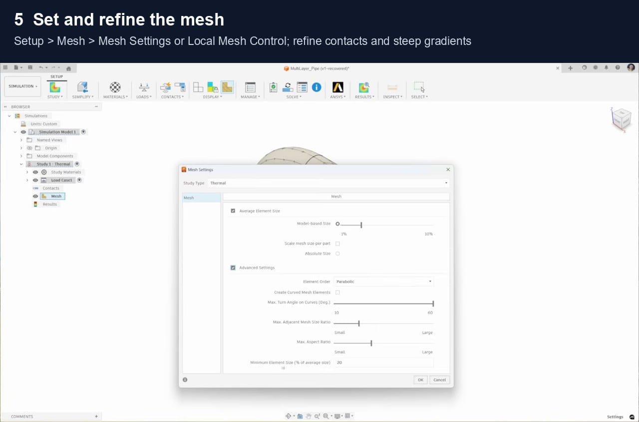
The mesh divides the solid into small finite elements that Fusion solves together. Smaller elements capture steep temperature changes more accurately but take longer to solve. Choose Generate Mesh, then use Local Mesh Control at contacts, fin roots and other areas where temperature may change quickly.
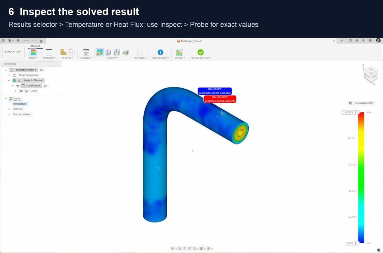
Temperature shows how hot each location becomes. Heat flux shows the rate and direction of heat flow through an area, while a temperature gradient describes how quickly temperature changes over distance. Probe the hottest point, inspect the heat path, then refine the critical mesh until the important values change only slightly.
Checks
Before using the result
Confirm that the hottest location makes physical sense, contacts are complete, and the imposed heat has a realistic path to ambient or a controlled-temperature boundary. Compare a known temperature or hand calculation where possible.
Learn it on video
Watch a thermal study run end to end
Autodesk's own walkthrough covers the same steps as this page. The Efficient Engineer video explains what the solver is doing underneath.
The Efficient Engineer: understanding the finite element method
Autodesk: simulation help documentation
Sources
References
The workflow is rephrased from Autodesk documentation. Demo values are teaching assumptions, not design limits.
Related articles

3D Printing Theory and Material Properties
Understand layers, stiffness, strength, toughness, heat resistance and slicer settings before building your next prototype.

Common 3D Printer Problems
A menu of common 3D printer problems, from power and extruder faults to filament, bed, temperature, motion, software and print-quality issues.

3D Printing on the Bambu Lab X1E
Use the X1E by matching the X1-series profile, secure network option, active chamber and filament before sending the job.