
A successful print starts with three decisions: what the part must do, which material suits that job, and how to build its layers. Use this guide before preparing your MIC prototype.
1. From a model to a printed part
Fused filament fabrication (FFF), also called FDM, builds an object one layer at a time. Feed rollers push thermoplastic filament into a heated hot end. The nozzle lays down a narrow bead; the material cools and bonds to the previous layer.
Unlike milling, which removes material from a block, additive manufacturing puts material where the design needs it. Hollow interiors are possible, but supports, brims and colour changes can still create waste.
- Model: make a design in Fusion or download a suitable model. Check its dimensions and reuse licence.
- Prepare: select the actual printer, nozzle, build plate and filament in Bambu Studio. Match the loaded filament before slicing.
- Slice: the slicer converts the 3D model into printer instructions: paths, extrusion, temperatures and other machine actions.
- Preview: inspect the layers, unsupported areas, print time and material estimate.
- Print and test: check the first layer, let the plate cool, remove the part and check its fit and function.
Choose your printer and follow its operating guide
2. What does a material property tell you?
Strong, stiff and tough mean different things. A rigid bracket, a drop-resistant case and a flexible bumper need different combinations of properties.
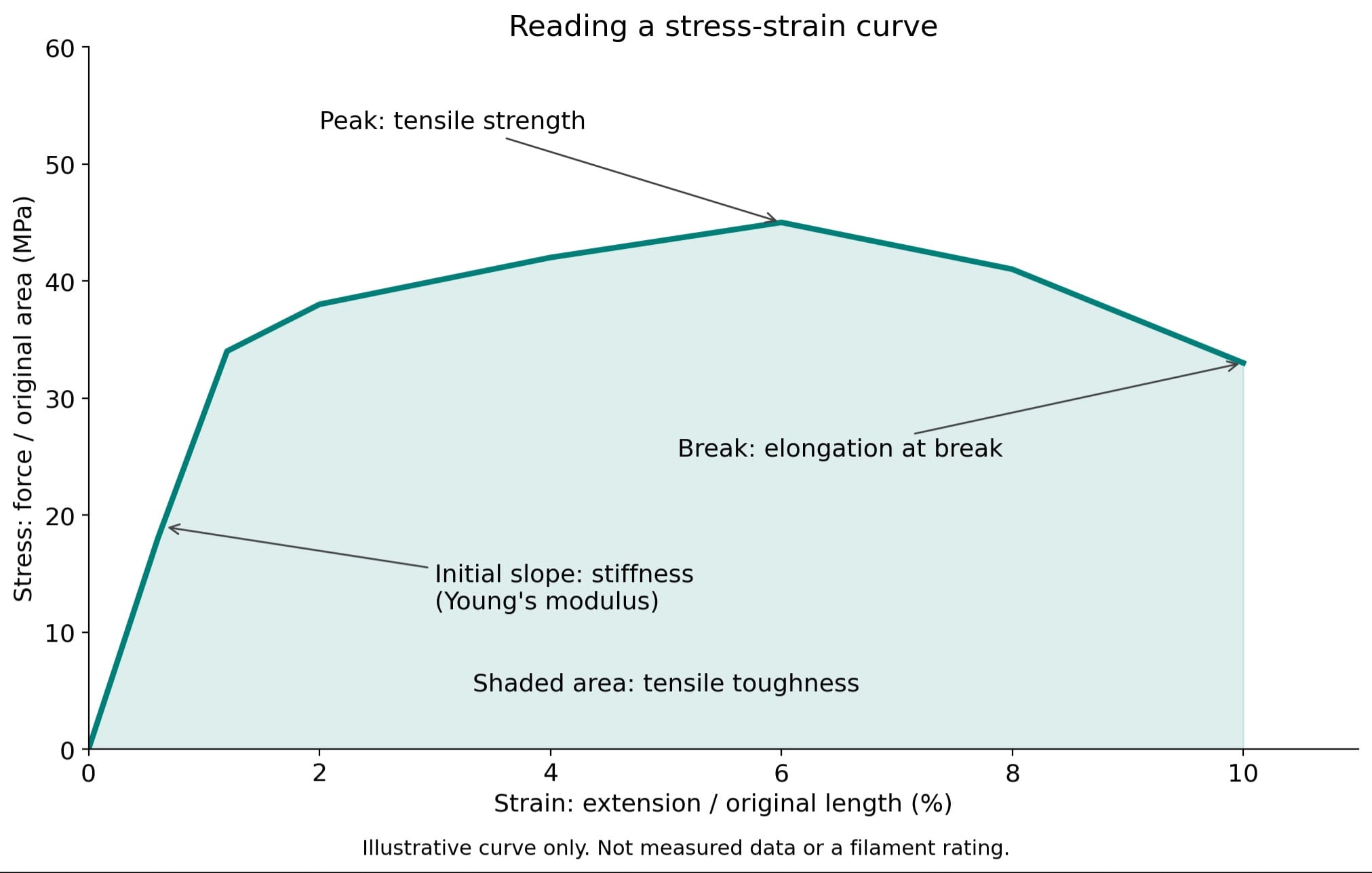
Stress and strain
Stress = force / original cross-sectional area. It describes how concentrated a load is. A 100 N pull on a 10 mm² section gives 10 MPa, because 1 N/mm² = 1 MPa. This is a simple uniform-tension example, not a safe working-load rating.
Strain = extension / original length. If a 50 mm test section stretches by 0.5 mm, its strain is 0.01, or 1%. Thin corners, holes and layer interfaces can experience much higher local stress than a simple average predicts.
Stiffness: how much does it bend?
Young's modulus, E, describes resistance to elastic stretching. It is the initial stress-strain slope. Higher E means less stretching at the same stress, within the linear elastic range. Elastic deformation recovers when the load is removed.
A sensor mount needs enough stiffness to keep its position. Shape matters too: adding a rib or increasing a bracket's thickness can reduce bending without changing the material. A bending modulus from a datasheet comes from a different test and should not simply be treated as Young's modulus.
Strength: when does it permanently deform or fail?
Yield strength marks the onset of substantial permanent deformation, where a defined yield point or offset is available. Ultimate tensile strength is the highest engineering stress reached in the tensile test. Neither is automatically an allowable load for your printed part.
A hook can be stiff but snap suddenly. Keep a margin below failure and test the actual printed geometry, orientation and loading direction.
Toughness and ductility: how does it fail?
Toughness is the energy absorbed before fracture. The area under a tensile stress-strain curve estimates tensile toughness per unit volume. Impact resistance is measured in a separate rapid-loading test; compare results only when the method and specimen conditions match.
Ductility describes the ability to deform plastically before breaking, often reported as elongation at break. A ductile part may bend before failure; a brittle one may break with little warning. A protective case needs impact performance, not just a high tensile-strength number.
Hardness is not stiffness
Hardness describes resistance to local indentation. Flexible TPU is often labelled with a Shore A hardness, such as 95A. That number does not mean 95% infill or a strength of 95 MPa. Wall thickness and infill still change how a TPU part feels.
3. Heat, time and the environment
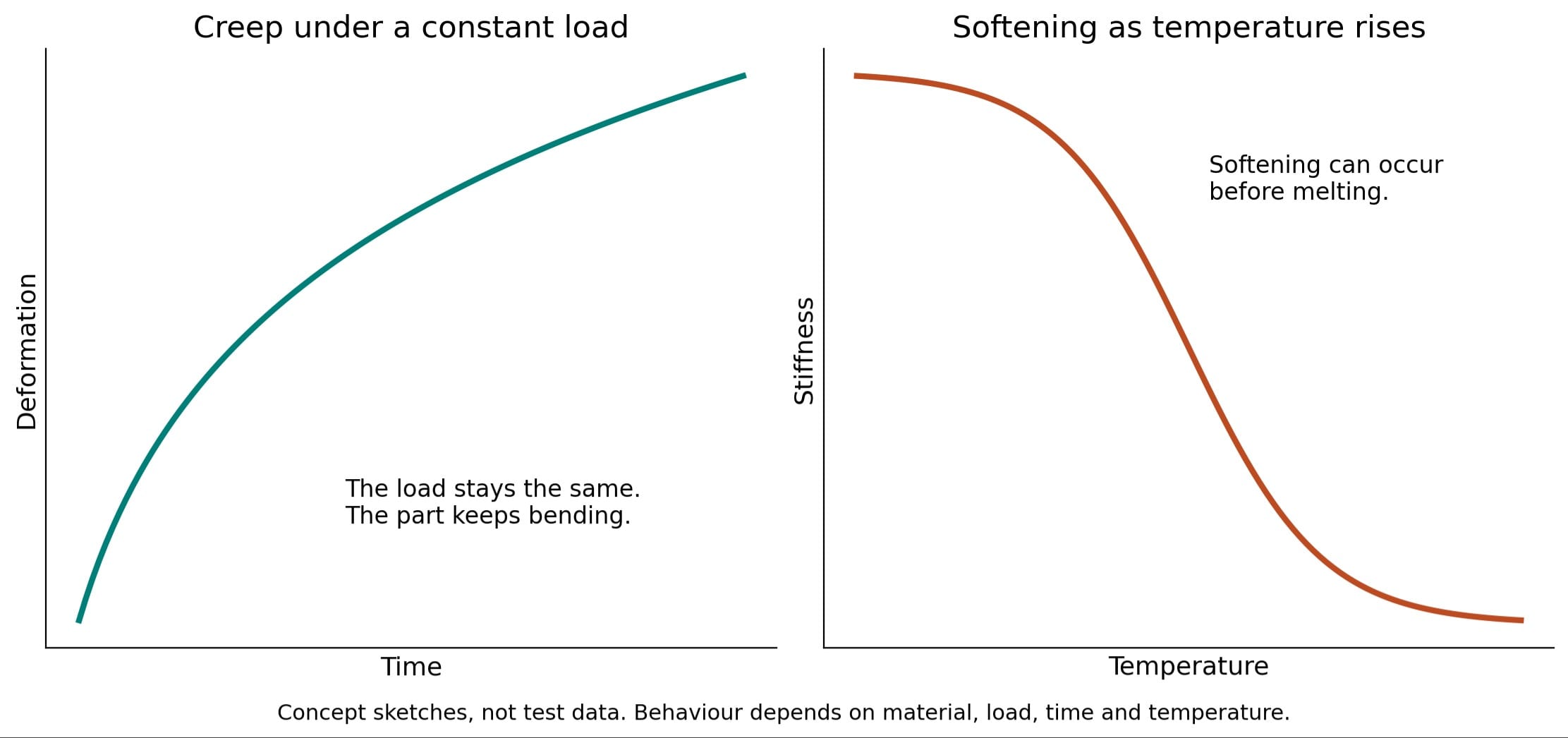
Heat resistance: nozzle temperature is a processing setting, not the temperature a finished part can safely withstand. The glass-transition region, Tg, is associated with softening of the amorphous phase. Heat-deflection temperature, HDT, measures deformation under specified test conditions. Neither alone is a continuous-use temperature rating.
Creep: plastic can keep deforming under a constant load. A loaded shelf bracket or tight clamp may gradually move even if it did not break during assembly. Test over the intended duration and temperature.
Moisture and weather: wet filament may print poorly; moisture can also change a finished polymer's properties. Nylon is especially moisture-sensitive. UV exposure and outdoor temperature cycles matter for outdoor parts. Use the material supplier's drying instructions and an appropriate filament dryer.
Density: mass per unit volume affects weight. The mass of a print also depends on its walls, shells and infill. Use the slicer's mass estimate to compare designs, then weigh the finished part if weight matters.
4. Match the filament to the job
Start with the function, not a single ranking of the strongest plastic. Grades, additives and printing conditions can change these general tendencies.
| Material | Useful starting application | Main trade-off |
|---|---|---|
| PLA | Fit checks, display models, low-load indoor prototypes | Easy to print and usually stiff; standard grades can be brittle and soften in warm conditions. |
| PETG | Tool holders, housings and functional prototypes | Often tougher than standard PLA, but can string and still creep under sustained load. |
| ABS | Impact-resistant housings and warmer indoor applications | More demanding shrinkage control; use suitable enclosure and ventilation. |
| ASA | Outdoor sensor covers and fixtures | Useful UV/weather resistance; enclosure and ventilation are important. |
| TPU | Bumpers, grip pads and flexible feet | Flexible rather than rigid; check the exact grade's feed-system compatibility. |
| PA / nylon | Wear-resistant mechanisms and functional parts | Drying and moisture conditioning are important; use the grade's technical data. |
Explore filament types and application examples
Compare datasheets using the same test method, print direction, conditioning and temperature. Values from injection-moulded samples are not interchangeable with FFF print results. Plant-derived PLA is not a promise that a printed object will readily biodegrade at home.
5. Turn the theory into slicer choices
Orientation: place the layers for the load
Printed parts are anisotropic: their properties depend on direction. The deposited roads and bonds between layers do not behave identically. Loads that pull layers apart can expose a weak direction.
For a bracket, think about the pulling and bending direction before placing it on the plate. Balance load direction, support marks and bed contact. Auto Orient is a useful starting point, not an engineering check. Changing to gyroid infill does not remove layer-direction effects.
Layer height: detail versus time
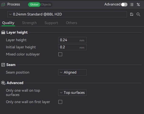
For a typical 0.4 mm nozzle, a 0.20 mm standard profile is a practical starting point. Use the printer profile's supported range. Smaller layer height improves vertical detail, not automatically the smallest line the nozzle can draw in the horizontal plane.
Walls and shells: the outside carries load too
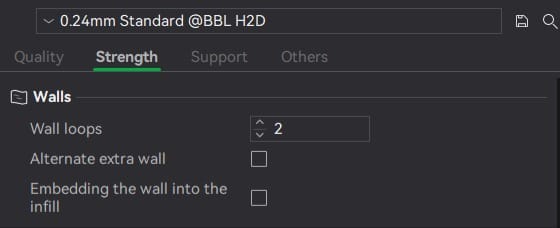
Walls form the sides; top and bottom shells close the part. Check both thickness and layer count. As a simple example, five solid layers at 0.20 mm nominal height total 1.0 mm. Thin features may not fit the requested number of walls, so inspect the sliced preview.
Infill: support the inside without making everything solid
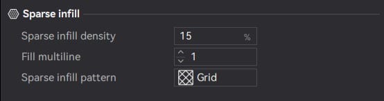
Infill supports top surfaces and contributes to the part's mechanical response. Start with a standard profile for a fit prototype, then change one setting at a time. High infill cannot fix weak layer bonds, sharp internal corners or poor orientation.
Supports: give overhangs something to rest on
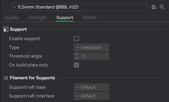
An overhang extends beyond the layer below. A bridge spans between supported ends. Their printable limits depend on material, cooling, geometry and settings, not one universal angle. Reorienting or splitting a model can reduce support use. Support interfaces help separate the support from the model but still leave surface marks.
Bed adhesion: keep the first layer flat
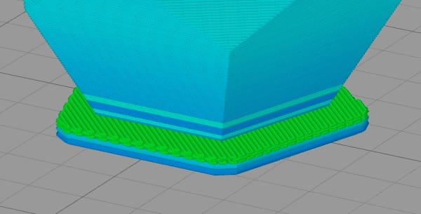
Cooling causes contraction. If the resulting forces overcome adhesion, corners can lift: this is warping. Use the correct clean plate, material profile and suitable room conditions. A brim may help, but it does not fix an oily plate or incorrect setup.
6. Run a small design test
- Write the requirement: for example, hold a sensor in position indoors, without noticeable movement during use.
- Choose material and orientation: explain which property matters and which direction carries the load.
- Print a small test piece: test the clip, hole or joint before printing the full enclosure.
- Measure: record fit, mass, print time and deflection under a modest known load. Keep people clear of a part that might break.
- Change one variable: try wall thickness, orientation or material, keeping the other settings the same.
- Record and repeat: compare multiple samples. A single successful print is not proof of reliability.
Tolerances: model dimensions and printed dimensions differ. Holes, mating faces and moving joints need clearance. Print a small clearance test with the same printer, material and orientation; there is no single allowance that works for every fit.
Before sending the job: confirm filament mapping, dimensions, plate contact, supports, toolpaths and estimated time. During printing, stop for loose first-layer lines, lifted corners or a part that has detached. Keep hands away from moving or hot parts.
Browse print problems and troubleshooting
Sources and further learning
David Roylance: stress-strain curves and David Whisnant: polymer mechanical properties explain the mechanical-property concepts. The two concept graphs are original teaching illustrations.
- MIC 2 Sept 2026 3D Printing Slides: workshop sequence and Bambu Studio screenshots. The screenshots illustrate controls, not a universal settings preset.
- Bambu Lab filament comparison and technical-data links
- Prusa filament material guide
- Prusa: layers and perimeters
- Prusa: infill
- Prusa: support material
- Prusa: modelling for 3D printing


