Static Stress Analysis Concepts
By Admin, 17/07/2026 · 4 min read
Engineering basics
Static Stress Analysis Concepts
Learn the material properties, loads, constraints and result terms used in a Fusion static stress study.
Foundations
Stress, strain and material behaviour
Start with the physical meaning of the values before entering them into a simulation.
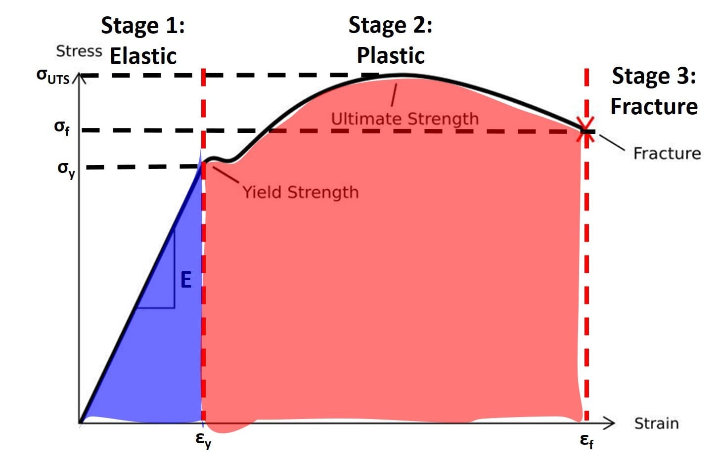
Read a stress-strain curve
Stress is internal force divided by area, so the same force creates more stress in a thinner section. Strain is change in length divided by original length. The initial straight part is elastic: remove the load and the material returns close to its original shape. Its slope is Young's modulus, so a steeper slope means a stiffer material. Yield strength marks the start of significant permanent deformation; beyond it, a linear static study is no longer a complete description.
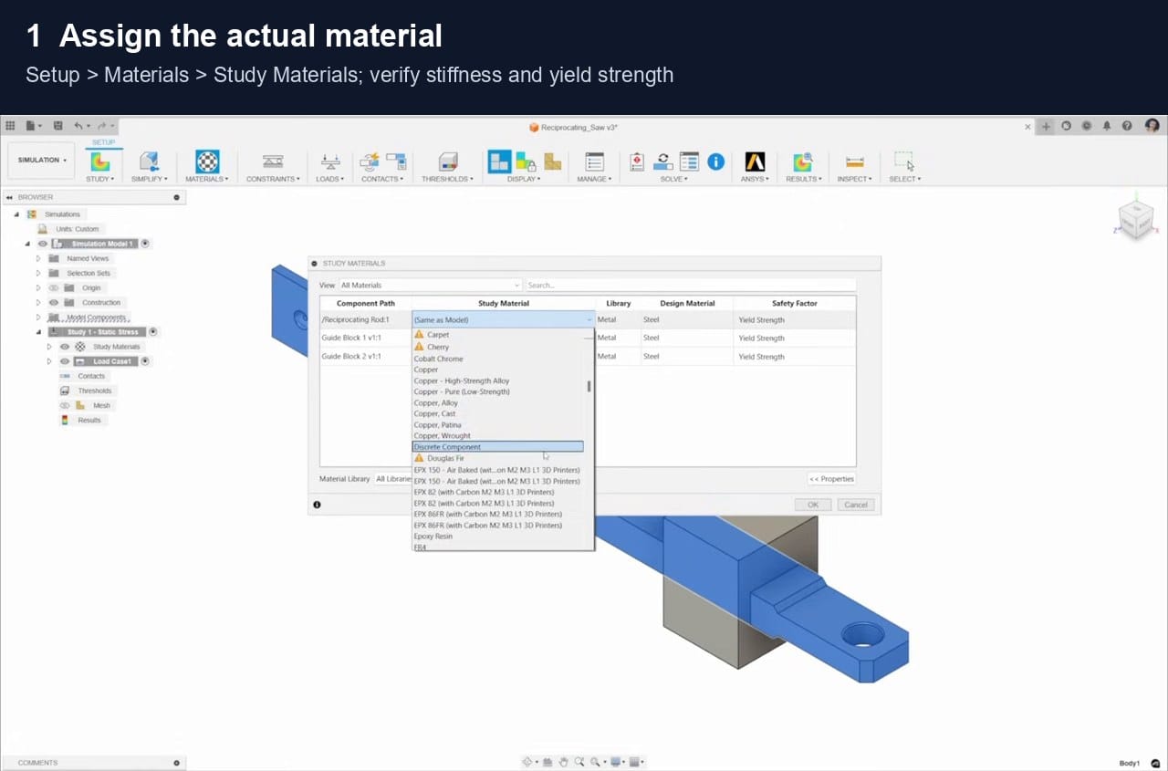
Young's modulus, Poisson's ratio and yield strength
Young's modulus controls elastic stiffness and therefore strongly affects displacement. Poisson's ratio describes the sideways contraction caused by lengthwise stretching; common metals are often near 0.3, but the exact value must come from the actual material data. Yield strength is used to judge when a ductile material begins to deform permanently. Use supplier or tested properties for the correct alloy, temper, print direction and temperature rather than relying on a similarly named library material.
Model setup
Loads, supports and the finite-element model
A precise solver cannot correct an unrealistic load path or support condition.
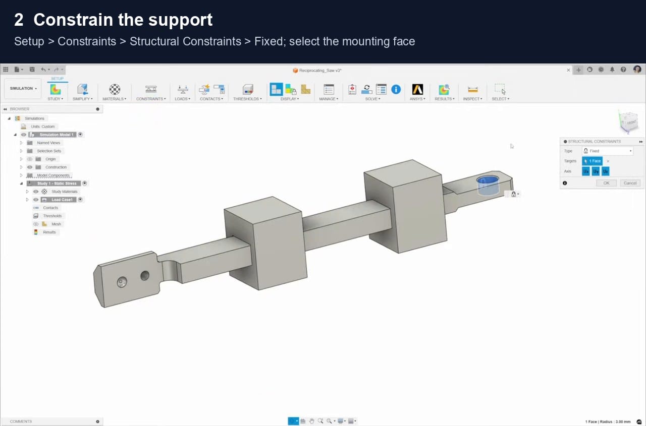
Constraints and reaction forces
Constraints represent the surfaces that stop or guide movement. A Fixed constraint blocks translation in all three directions and can make a model unrealistically stiff when the real part is bolted, pinned or able to slide. Reaction forces are the forces created at these supports. Their total should balance the applied load; if a 500 N downward load is applied, the vertical support reaction should be about 500 N upward.
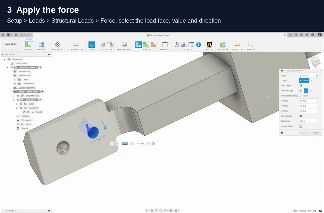
Force, load direction and stress concentration
A force has magnitude and direction. Apply it over the surface that carries the real load, not at an arbitrary point. Bending creates the highest normal stress furthest from the neutral axis, while sharp corners, holes and sudden thickness changes can concentrate stress. A fillet spreads the load path and usually reduces the peak compared with a perfectly sharp corner.
Finite elements and mesh convergence
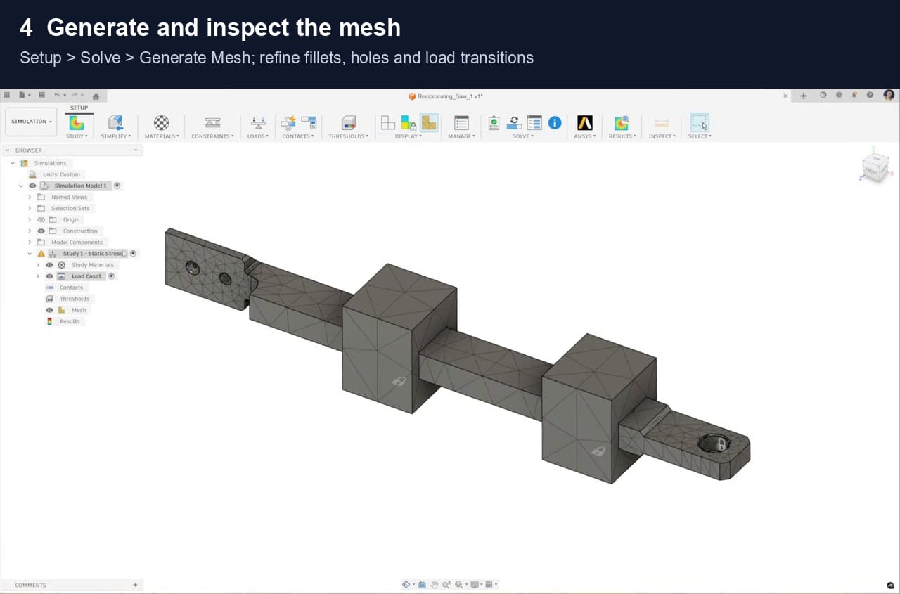
Finite-element analysis divides the model into many small elements and solves their connected behaviour. A coarse mesh is faster but may miss a steep stress gradient. Refine fillets, holes, contacts and load transitions, then solve again. A result is converging when useful values such as displacement and stress away from a singular edge change only slightly as the mesh becomes finer.
Results
How to interpret the colour plots
Use the numbers, assumptions and load path together; colour alone does not determine whether a design is safe.
Von Mises stress, safety factor and displacement
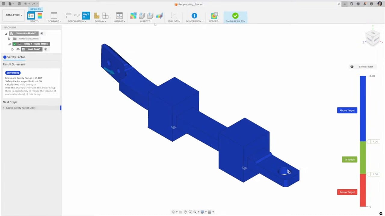
Von Mises stress combines a three-dimensional stress state into one equivalent value for checking yielding in ductile materials. Fusion calculates safety factor as material strength divided by equivalent stress; 1 means the calculated stress has reached the selected strength limit. Displacement shows movement, but the displayed deformed shape may be visually exaggerated. Check the numerical value, reaction balance, mesh convergence and whether the linear-elastic assumptions remain valid.
Limits of the model
Sources
References
Figures and concepts are drawn from the sources below. The stress-strain figure is used from Engineering LibreTexts under its stated Creative Commons licence; Fusion screens come from Autodesk's official walkthrough.
Engineering LibreTexts: stress and strain
Autodesk: static stress assumptions
Autodesk: safety factor calculation
Autodesk: reaction forces
Autodesk Fusion static stress video
The Efficient Engineer: stress and strain
The Efficient Engineer: Poisson's ratio
The Efficient Engineer: finite-element method
The Efficient Engineer: failure criteria
Related articles

3D Printing Theory and Material Properties
Understand layers, stiffness, strength, toughness, heat resistance and slicer settings before building your next prototype.

Common 3D Printer Problems
A menu of common 3D printer problems, from power and extruder faults to filament, bed, temperature, motion, software and print-quality issues.

3D Printing on the Bambu Lab X1E
Use the X1E by matching the X1-series profile, secure network option, active chamber and filament before sending the job.