Collision sensor
By Admin, 07/07/2026 · 4 min read
Sensor module
Collision sensor
Module 08 in the 37-in-1 kit. Detects a physical bump. Start by changing one physical condition and watching the reading respond.
Source image
Match the physical module
Use this source photo to identify the module before wiring it. The photo is saved from the checked 37-in-1 kit guide.
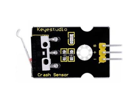
What it detects
Detects a physical bump.
This is the main signal to test before adding displays, motors, buzzers, or game logic.
How it works
What you need
Starter parts
Keep the first circuit small and add displays or motors later.
Try first
Trigger an LED when the lever is touched.
This is the quickest way to see the module reading change.
Connections
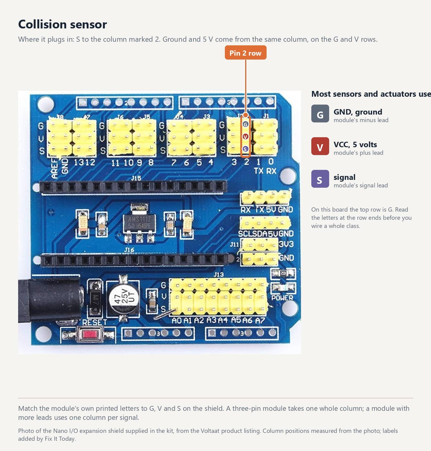
Wiring to the Arduino Nano on its expansion shield
Plug into the digital bank of headers. The pin numbers below match the sketch further down this page; change one and change the other.
Before you power it
Plug the module into the header listed above, black lead to ground.
Copy the sketch below, upload it, and open Tools > Serial Monitor at 9600 baud.
Change the physical condition the module senses and watch the reading or output respond.
Starter sketch
Code you can copy and upload
Set the pin constants at the top of the sketch to match the header you plugged the module into, then upload it and open Tools > Serial Monitor at 9600 baud.
Build next
Make a bumper input for a small moving model.
Turn the raw reading into a small useful interaction.
Reference
Source guide and step-by-step builds
Use the source guide for the exact wiring diagram, and the workshop guides for a full worked build on this board.
Arduino Nano and DHT11 electronics workshop
Arduino Nano and I/O expansion shield wiring
Install Arduino IDE on Windows or Mac
37-in-1 kit index
Survey and feedback
Help improve MakerAccess
Have an idea for what MakerAccess should stock, improve, or explain next? Share it in the survey. If you bought or used a product and want to comment on the item itself, use the product feedback form.
Do the surveyProduct feedback form