Fusion for 3D Printing
By Admin, 15/07/2026 · 5 min read
Fusion
Fusion for 3D Printing
Learn the complete path from a new Fusion file to a dimensioned 3D model that is ready to check in a slicer.
Learn it on video
Follow along on video
The official Autodesk series plus two beginner walkthroughs. Worth watching before the tutorial below if you have never opened Fusion.
Autodesk Fusion: sketching made easy
Autodesk Fusion: the Sweep command
3D Printer Academy: Fusion beginners guide with an example project
Aviv Makes Robots: Fusion for absolute beginners
Autodesk: official Fusion tutorial library
Basics
How Fusion modelling works
Most printable parts begin as a 2D sketch. Dimensions set the size, constraints control relationships, and solid features such as Extrude, Hole and Fillet turn that sketch into an editable 3D model. The timeline records each feature so it can be changed later.
Before starting
Tutorial
Model a simple link bracket
Follow the real Fusion screens in order. Select each image to view it at full size.

1. Create and save a new design
Open Fusion in the Design workspace and select the plus button for a new design. Select Save, choose a project folder and give the file a useful part name. Saving first keeps versions and later exports associated with the correct design.
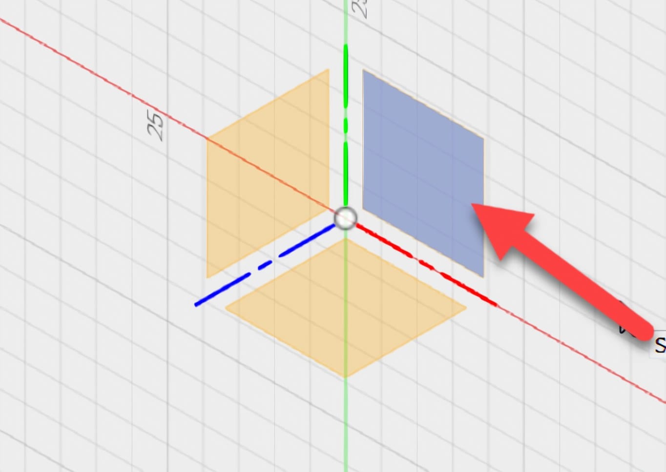
2. Start a sketch on an origin plane
Choose Solid > Create Sketch. Fusion displays the XY, XZ and YZ origin planes. Select the plane that gives the clearest main outline of the part; this example uses a vertical plane for the side profile. The chosen plane becomes the flat drawing surface.
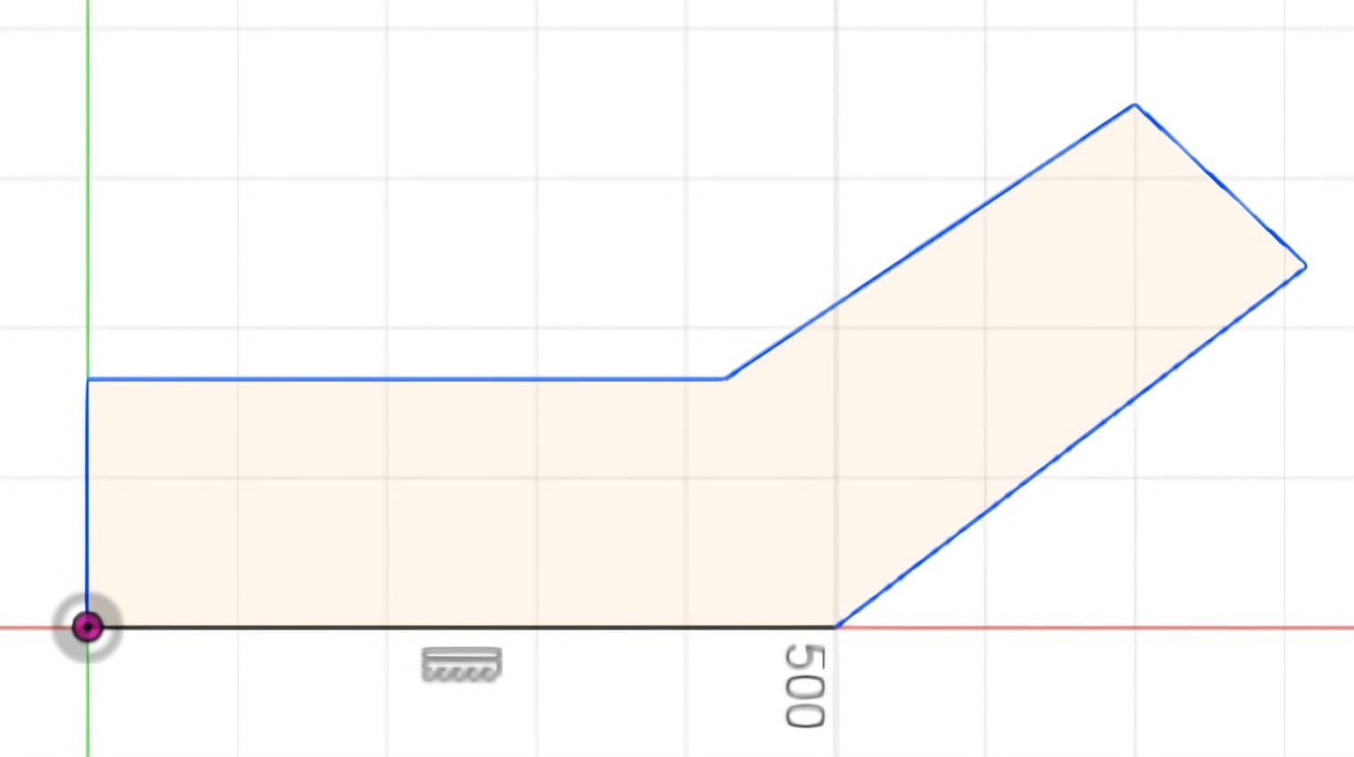
3. Draw one closed outline
Choose Sketch > Create > Line, or press L. Start at the origin and click each corner of the outer profile. Finish by clicking the starting point so the boundary is closed. A closed region is shaded and can become a solid; gaps or overlapping lines prevent a normal solid extrusion.
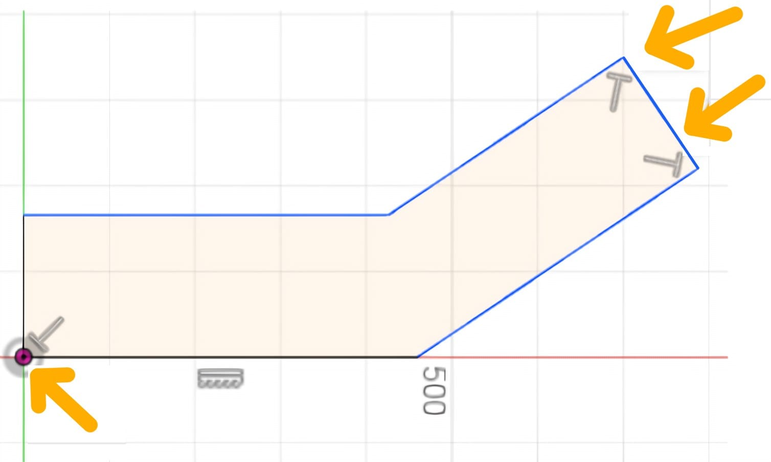
4. Add geometric constraints
Use Horizontal/Vertical, Perpendicular, Parallel, Equal, Coincident and Tangent only where each relationship describes the intended shape. Constraints control how geometry is related; dimensions control its measured size. Avoid using Fix simply to hide movement in an unfinished sketch.
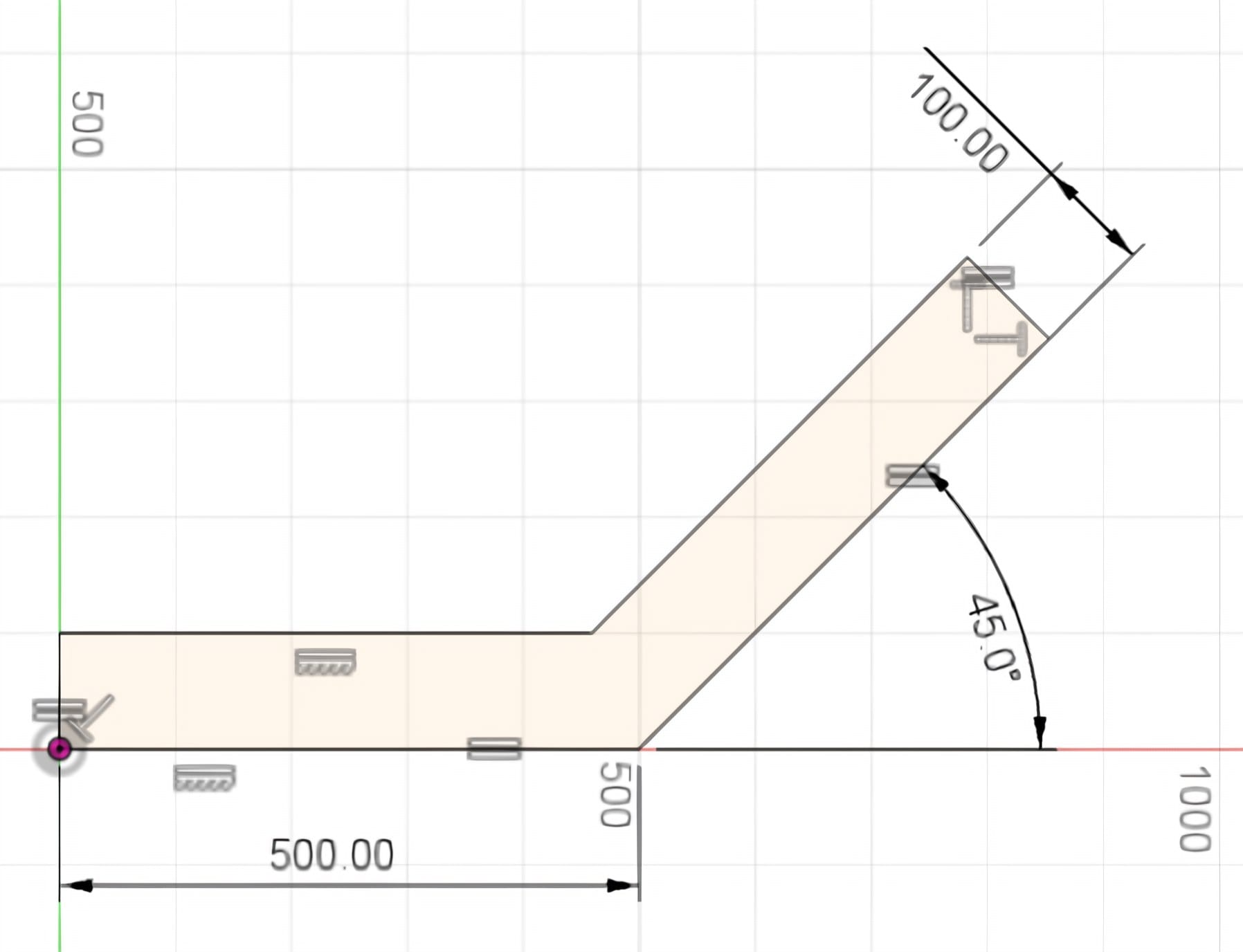
5. Set the size with dimensions
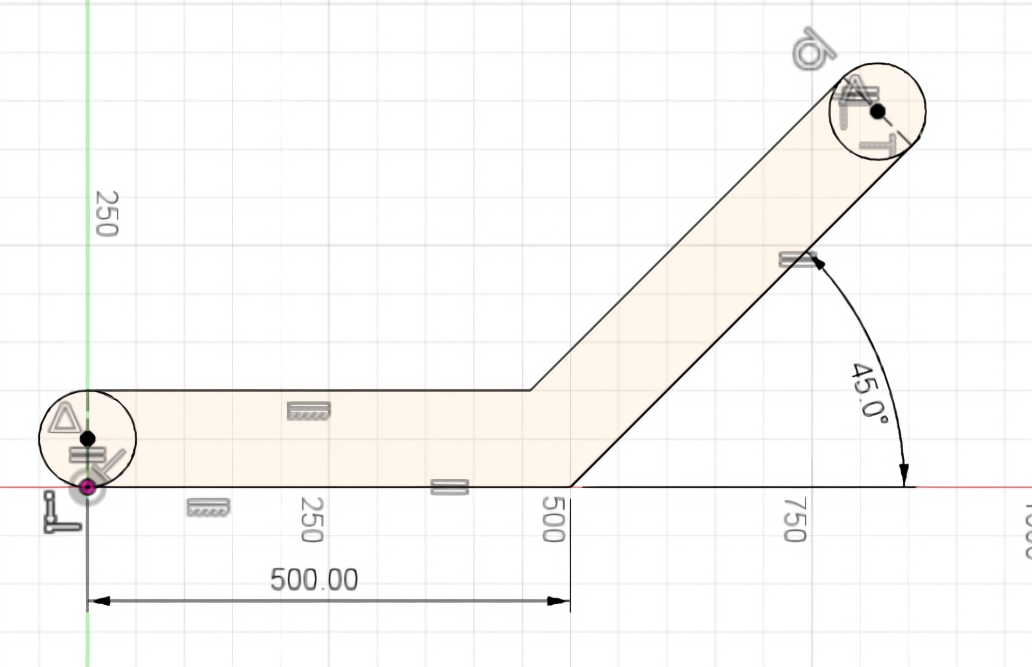
Choose Sketch > Create > Sketch Dimension, or press D. Select a line for length, two lines for spacing, or a circle for diameter, then enter the required value. Dimension the profile from the origin or another stable datum. Black geometry is fully constrained; blue geometry can still move.
6. Place hole centres with construction geometry
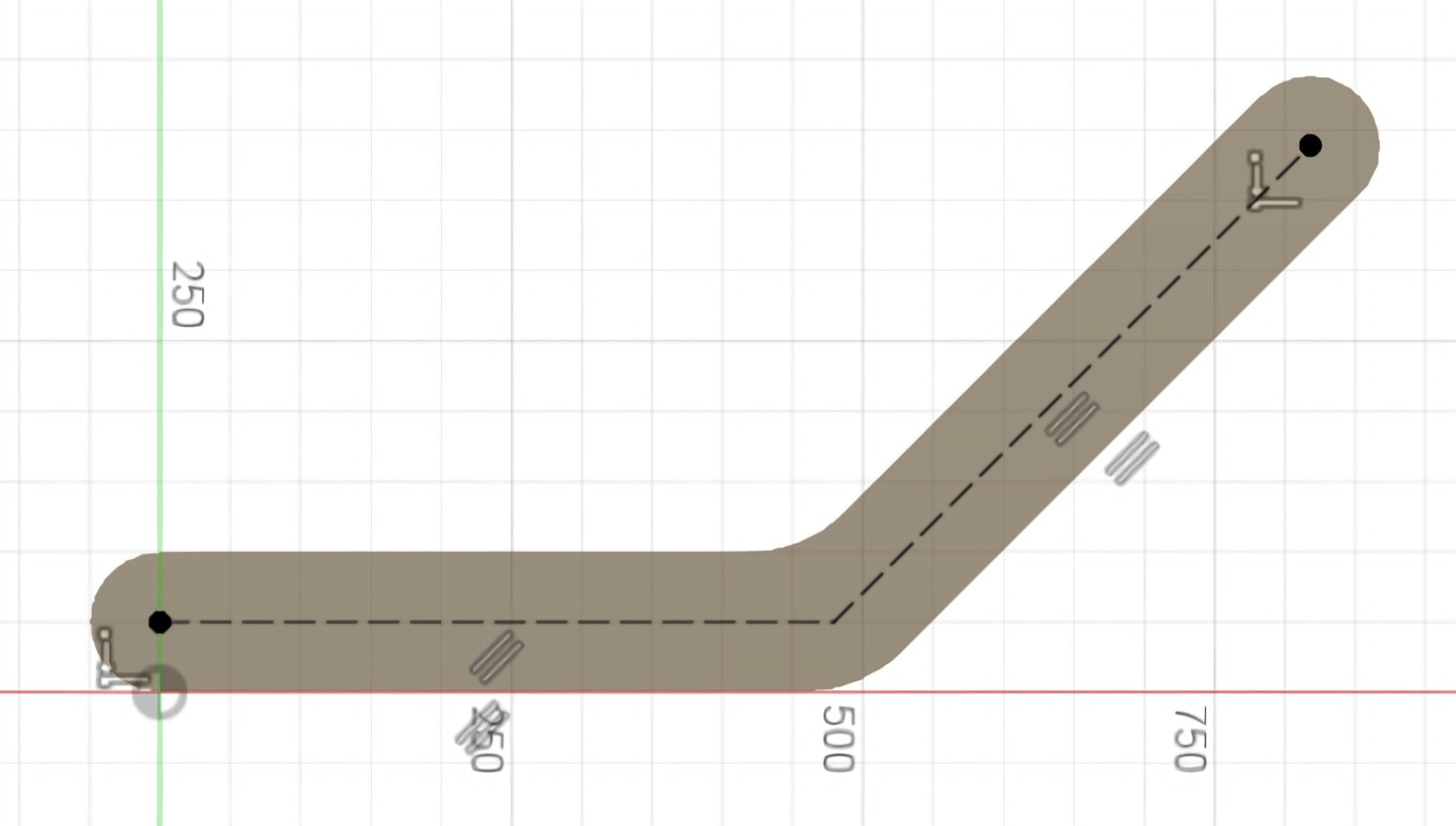
Use construction lines as references that do not become solid edges. Add Center Diameter Circles at the required hole centres and dimension their position and diameter. A hole should be located from functional datums rather than placed by eye.
7. Turn the sketch into a solid
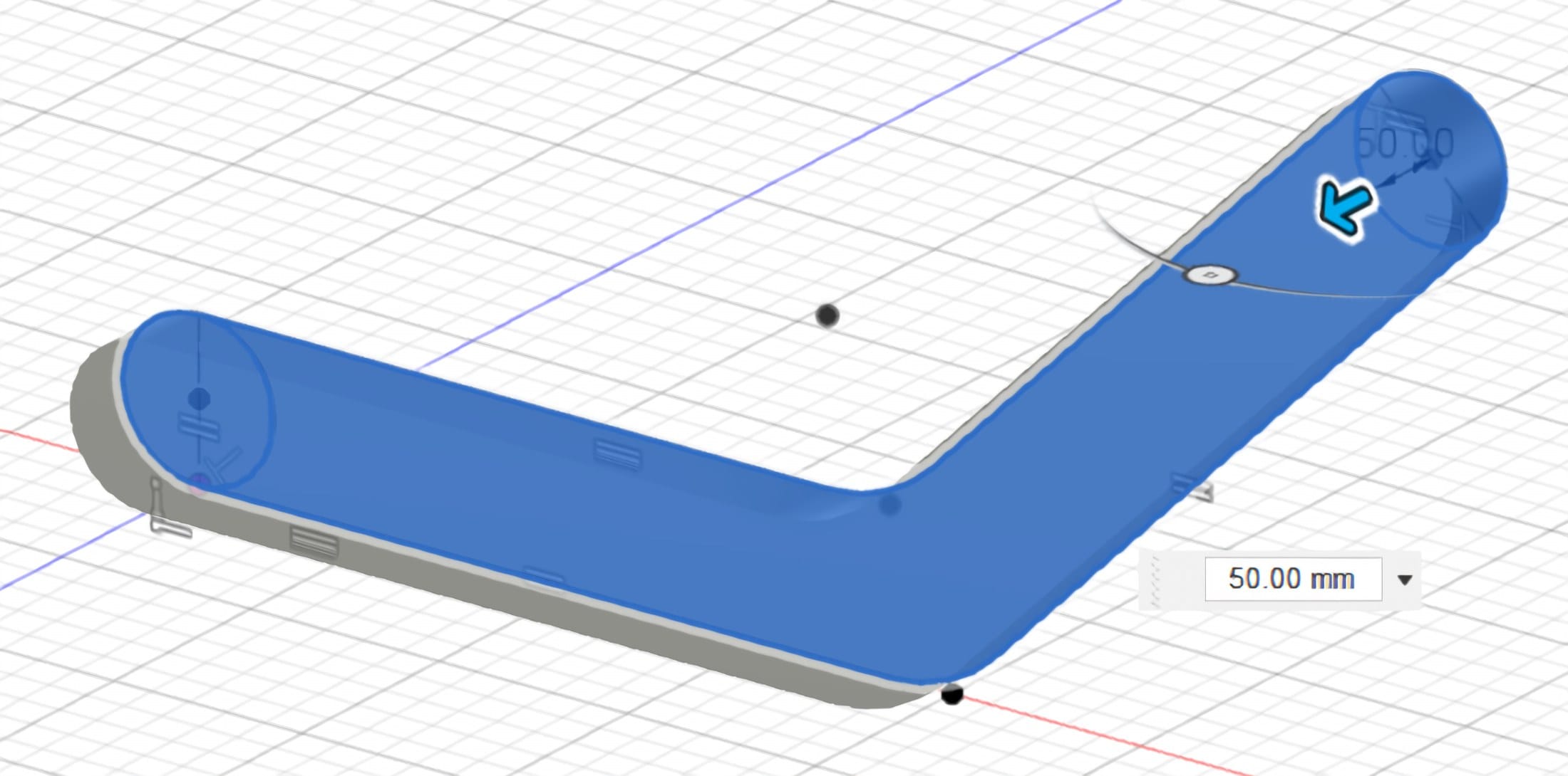
Select Finish Sketch, then choose Solid > Create > Extrude or press E. Select the shaded outer profile, enter the part thickness and set Operation to New Body for the first solid. Check the preview direction and select OK. The new feature appears in the timeline.
8. Add features on a solid face
Select a flat face and choose Create Sketch. Project or reference existing geometry only where needed, then add the next holes, slots or cut-outs. Finish and dimension this sketch using the same constraint-first process. Sketches on faces remain linked to the earlier solid feature.
9. Cut the holes through the part
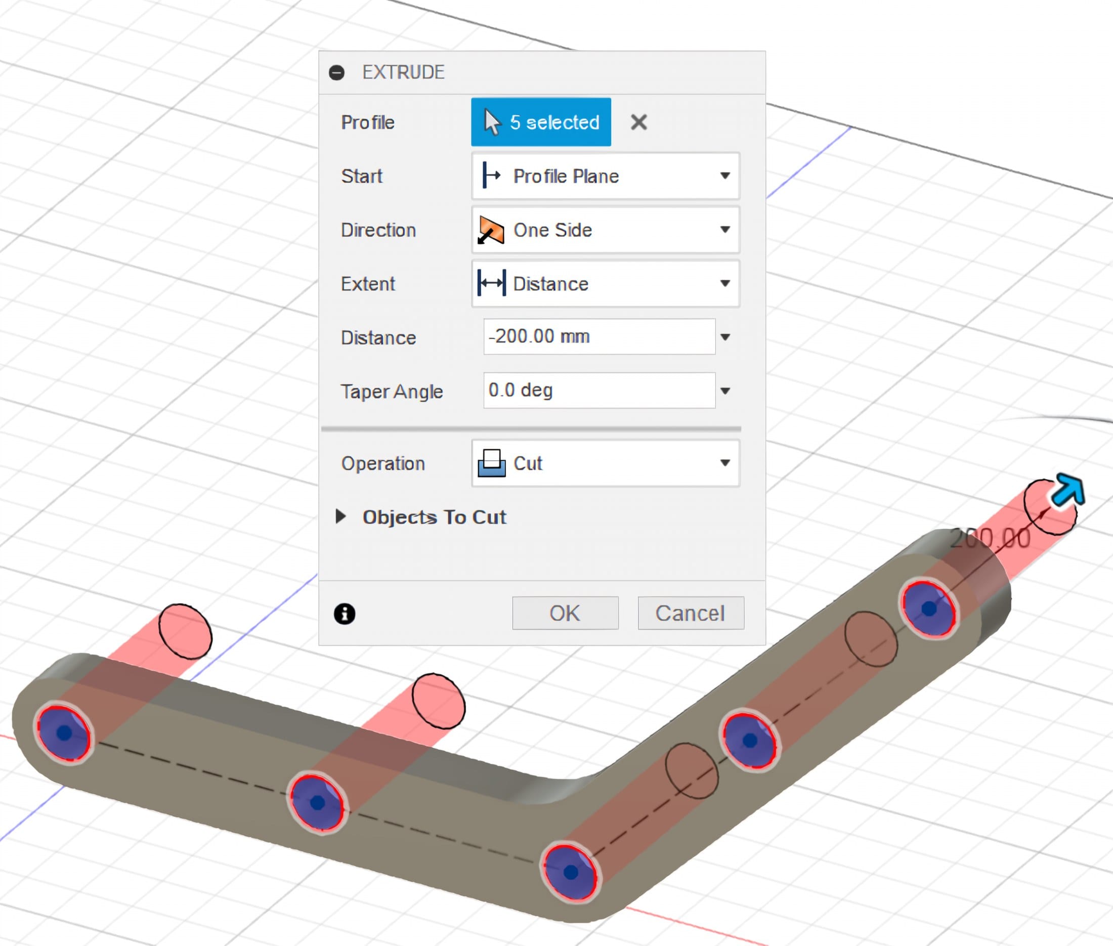
Select the circular profiles and choose Extrude. Set Operation to Cut and Extent to All when the holes must pass through the complete thickness. The Hole command is another good option when a standard drilled, counterbored or countersunk hole is required.
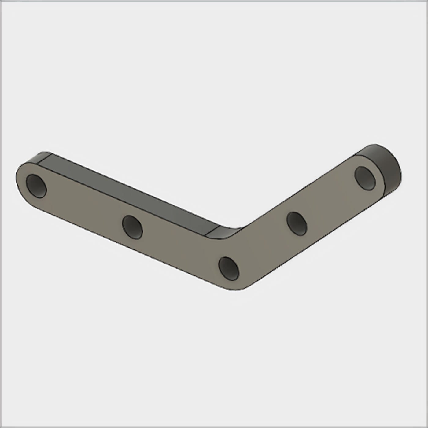
10. Finish and inspect the model
Use Modify > Fillet on sharp load-bearing transitions and Chamfer where an assembly needs a lead-in. Choose Inspect > Measure to check overall length, thickness and hole diameters. Change an early dimension and confirm that the timeline rebuilds without warnings. The Autodesk practice dimensions shown in these figures must be adjusted to suit the intended printer, fastener and load.
Printing
Prepare the model for the slicer
A correct CAD model still needs a final size, orientation and mesh check before printing.
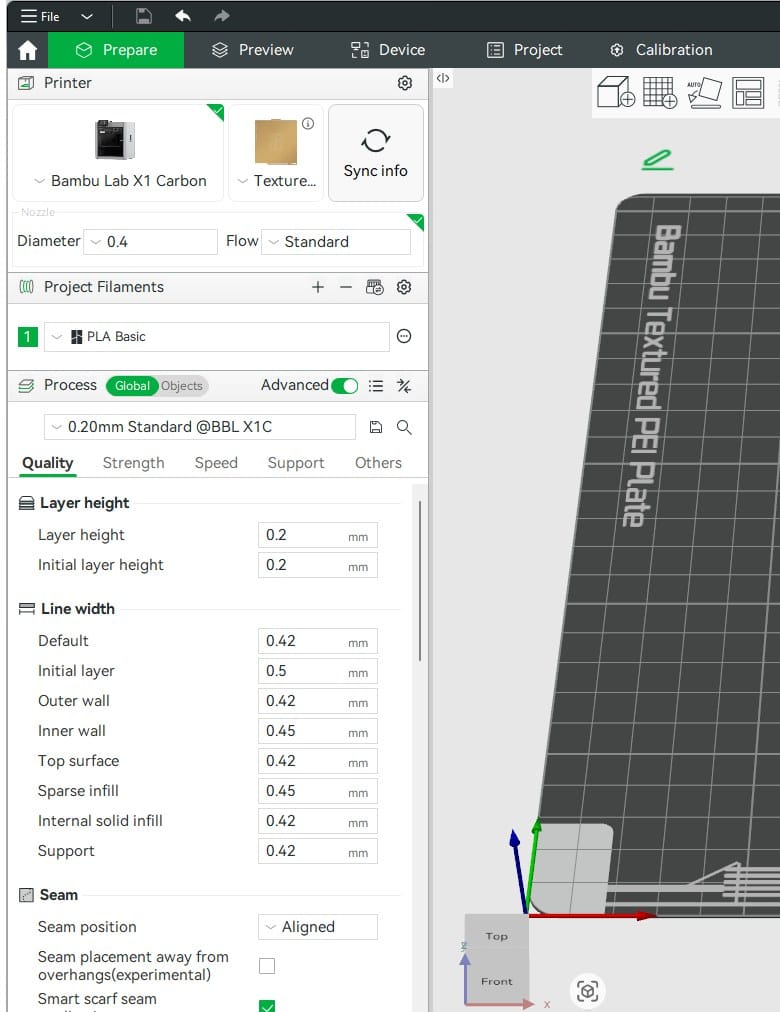
11. Export and check in Bambu Studio
In Fusion, right-click the component or body and choose Save As Mesh. Select 3MF, millimetres and a suitable refinement, then save the file. Import it into Bambu Studio, confirm the displayed dimensions, orient the strongest load path sensibly, select the correct printer and filament, then slice and inspect the preview before printing.
Check before printing
Continue
Focused Fusion guides
Use these lessons when the basic modelling sequence is familiar.
Draw a Printable Bracket in Fusion
Parametric Modelling in Fusion
Designing 3D-Printed Fits and Tolerances
Thermal Simulation in Fusion
Static Stress Analysis in Fusion
Static Stress Analysis Concepts
Sources
References
The modelling sequence and real Fusion figures are based on Autodesk's current beginner sketch and part-modelling documentation.
Related articles

3D Printing Theory and Material Properties
Understand layers, stiffness, strength, toughness, heat resistance and slicer settings before building your next prototype.

Common 3D Printer Problems
A menu of common 3D printer problems, from power and extruder faults to filament, bed, temperature, motion, software and print-quality issues.

3D Printing on the Bambu Lab X1E
Use the X1E by matching the X1-series profile, secure network option, active chamber and filament before sending the job.